Keywords: UBJ LBJ OTR SSL UPPER BALL JOINT LOWER BALL JOINT STABILIZER SHAFT LINK FRONT ANTI SWAY BAR LINK
Job: Replace 2 upper ball joints, 2 lower ball joints, 2 outer tie rods and 2 stabilizer shaft links.
Vehicle: 2005 GMC Envoy SLT 4WD 4.2L 6 cyl. 217,857 miles
My friendly tire service shop changed my engine oil and informed me that my right outer tie rod was in need of replacement. I thanked them for the information and contemplated my next move. To spend or to fix it myself that was the question.
I reasoned that If one steering component was worn then others cannot be far behind. I jacked under the A-arm and pried with a 3 ft wrecking bar. The left lower ball joint was loose. Not a lot, just a little. I made the decision to replace all the ball joints and tie rods and while I am in there the stabilizer shaft links too. The decision to replace the stabilizer shaft links was from a past job where I needed to remove one and found the threads seized into a rusty unserviceable mess. Now is the time to clean it up.
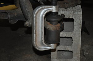
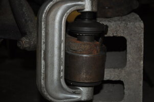
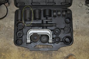
I spent about 3 hours researching the subject on this forum (and that other one) and judged the job doable but hardy. The Powerbuilt 23 pc. Ball joint Service Kit 46 was successfully used in several threads. I will use it too and got it as a loaner from AutoZone.
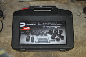 DSC_0040
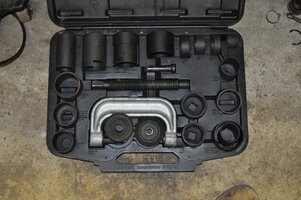 DSC_0041
In review I found the kit could not remove one of my lower ball joints and did some damage to the lower ball joint boots. Read on for more details .
I was also curious about experiences with various manufacturer’s suspension products. There was nothing definitive in the threads except the usual rants and accolades. HARDTRAILZ liked Detroit Axle and that was good enough for me. The fact that the cost was one quarter other brands had nothing to do with my decision. I purchased them on ebay. 2 upper ball joints + 2 lower ball joints and 2 stabilizer links for about $75. I purchased a la carte because the hardware was not shown on the special combo deals. I have since learned that the combos do include the same hardware.
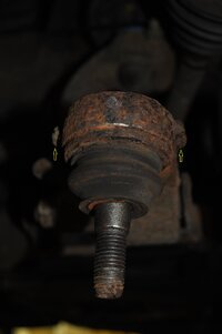
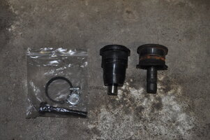
Here are some comparison shots of the new Detroit Axle parts against what I removed:
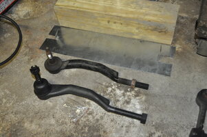 DSC_0006
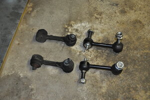 DSC_0007
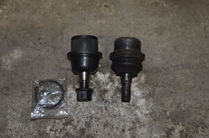 DSC_0008
 DSC_0009
My visual inspection and holding the parts in my hand could not reveal any substantial difference. Time will be the judge.
In the procedural descriptions, I have used the exact dimensions of the various tubes and cups of the ball joint press as the labels on the case were often approximate. Length refers to the outside wall length and does not include the receiver bump. The receiver is the end of the press with the hole, and the presser end is the screw side. The press elements are always listed from top (presser screw) to bottom.
I proceeded as follows:
1. Loosen wheel hub axle bolt, wheel lugs, jack car, remove tire.
2. Disconnect speed sensor wire at the plug on the chassis back to the steering knuckle. To disconnect the electric plug: first pull it straight perpendicular from the chassis frame(optional), then remove the grey safety lock by depressing the middle barb with a small screw driver while pulling, then disconnect the plug by squeezing the locking tab on the neck while pulling apart the plug assy. Disconnect the speed sensor cable clamps with a small screw driver prying up in the hood pocket.
3. Disconnect the brake line clamp on the back side of the steering knuckle.
4. Disconnect brake line mounting block on frame.
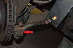
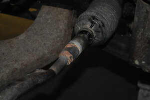
5. Outer tie rod removal: Before removing the outer tie rod, precisely measure the length from stud center to the inner tie rod jam nut junction. Use this measurement to adjust the new replacement tie rod. Pry loose the bellows squeeze clamp and push the bellows away from the inner tie rod shoulder. Adjust the steering so the bellows is not touching the parts about to be heated.
 DSC_0001
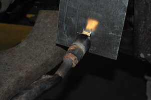
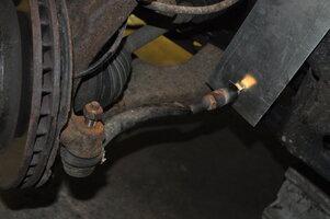
Position a heat shield to protect the bellows.
 DSC_0002
 DSC_0003
Use an oxy-acetylene torch to heat the jam nut to cherry red and balance some of the heat to the adjoining inner tie rod hex. Quickly remove torch and wrench the jam nut and inner tie rod free. Use a wet rag to cool the components. Don’t get water into the steering bellows. Don’t overheat the inner tie rod or melt the bellows. I did this without damage to bellows or inner tie rod. It is more heat resistant than one would think. Remove the outer tie rod from the steering knuckle and replace with new. Use tool GM J 24319-B
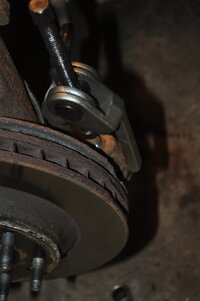 DSC_0004
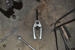 DSC_0005
Adjust new outer tie rod to the measured distance. Clamp the bellows in place with a new pinch clamp. McMaster Carr stock number 52545K57, diameter 1.125 – 1.250 x .281 wide stainless steel. https://www.mcmaster.com/catalog/125/337 and the tool 6541K67 https://www.mcmaster.com/catalog/125/338
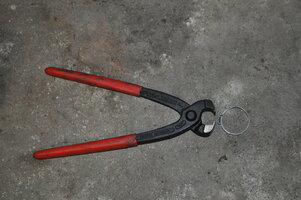 DSC_0010
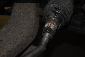 DSC_0011
Leave the outer tie rod unconnected to the steering knuckle to facilitate ball joint replacement.
6. Remove stabilizer link with cutting torch. Don’t bother trying to remove old rusty nuts. If you do, an odd ball 7mm allen wrench is required, and will probably strip during the removal process. Torching off the nuts is a whole lot easier.
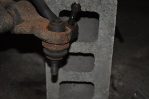
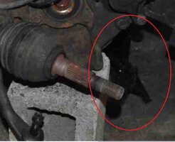
7. Replace the upper ball joint. Separate upper ball joint from upper control arm by removing the pinch bolt. The steering knuckle can now be tilted sideways so the ball joint press can project away from the vehicle fender. Use a lead hammer to knock the axle shaft inward while tilting the steering knuckle outward.
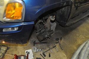 DSC_0015
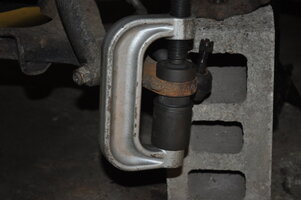
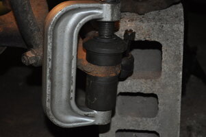
Remove the C-clamp from the old ball joint. Setup the press as follows: small presser stud, 15mm socket, receiver cup 2.160/2.240 OD x 1.982 id x 2.20 L
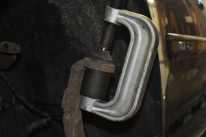 DSC_0017
The 15MM ½ inch socket is placed over the ball joint stud to act as a bearing surface to prevent the stud from cocking sideways.
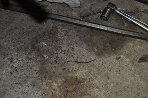
The Powerbuilt press requires a 7/8 inch socket. Use a breaker bar with a 2 ft pipe extension and a 3 ft wrecking bar as a counter torque element. The use of a ¾ in breaker bar would be recommended, but I used a ½ inch breaker bar and prayed that it would not snap. Luckily it did not.
To install the new upper ball joint set up the press as follows: small presser stud, presser adapter, tube 2.50 OD x 2.25 id x 1.70 L and receiving cup 2.125 od x 1.81 id x .84 L Sorry no picture. Install snap ring. Point grease Zerk towards the rear of the vehicle.
8. Separate lower ball joint from lower control arm. Use tool GM J 43631 Got it on ebay years ago.
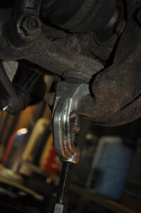 DSC_0018
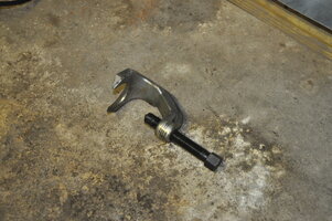 DSC_0025
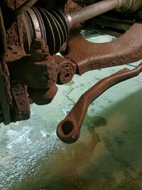
The steering knuckle assembly weighs about 50 lbs. I could easily handle it alone but be ready for it to drop as soon as the ball joint nut is removed. Tip the assembly to clear the axle. Support the steering knuckle assembly on a block positioned in the rear of the wheel well, The brake line remains connected. Use some wire ties to lift the axle shaft out of the way.
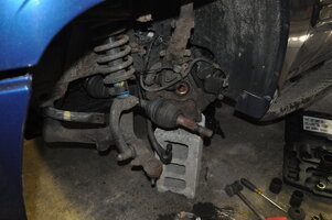 DSC_0020
9. Replace lower ball joint
Use a hammer and cold chisel to bend the lower ball joint flared retainer flange straight.
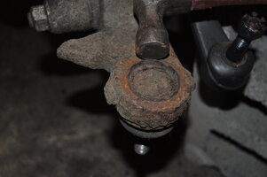 DSC_0021
continued
Replace 4 Ball Joints, 2 Tie Rods and 2 Stabilizer Links: Part 2
Job: Replace 2 upper ball joints, 2 lower ball joints, 2 outer tie rods and 2 stabilizer shaft links.
Vehicle: 2005 GMC Envoy SLT 4WD 4.2L 6 cyl. 217,857 miles
My friendly tire service shop changed my engine oil and informed me that my right outer tie rod was in need of replacement. I thanked them for the information and contemplated my next move. To spend or to fix it myself that was the question.
I reasoned that If one steering component was worn then others cannot be far behind. I jacked under the A-arm and pried with a 3 ft wrecking bar. The left lower ball joint was loose. Not a lot, just a little. I made the decision to replace all the ball joints and tie rods and while I am in there the stabilizer shaft links too. The decision to replace the stabilizer shaft links was from a past job where I needed to remove one and found the threads seized into a rusty unserviceable mess. Now is the time to clean it up.
I spent about 3 hours researching the subject on this forum (and that other one) and judged the job doable but hardy. The Powerbuilt 23 pc. Ball joint Service Kit 46 was successfully used in several threads. I will use it too and got it as a loaner from AutoZone.
 DSC_0040
 DSC_0041
In review I found the kit could not remove one of my lower ball joints and did some damage to the lower ball joint boots. Read on for more details .
I was also curious about experiences with various manufacturer’s suspension products. There was nothing definitive in the threads except the usual rants and accolades. HARDTRAILZ liked Detroit Axle and that was good enough for me. The fact that the cost was one quarter other brands had nothing to do with my decision. I purchased them on ebay. 2 upper ball joints + 2 lower ball joints and 2 stabilizer links for about $75. I purchased a la carte because the hardware was not shown on the special combo deals. I have since learned that the combos do include the same hardware.
Here are some comparison shots of the new Detroit Axle parts against what I removed:
 DSC_0006
 DSC_0007
 DSC_0008
 DSC_0009
My visual inspection and holding the parts in my hand could not reveal any substantial difference. Time will be the judge.
In the procedural descriptions, I have used the exact dimensions of the various tubes and cups of the ball joint press as the labels on the case were often approximate. Length refers to the outside wall length and does not include the receiver bump. The receiver is the end of the press with the hole, and the presser end is the screw side. The press elements are always listed from top (presser screw) to bottom.
I proceeded as follows:
1. Loosen wheel hub axle bolt, wheel lugs, jack car, remove tire.
2. Disconnect speed sensor wire at the plug on the chassis back to the steering knuckle. To disconnect the electric plug: first pull it straight perpendicular from the chassis frame(optional), then remove the grey safety lock by depressing the middle barb with a small screw driver while pulling, then disconnect the plug by squeezing the locking tab on the neck while pulling apart the plug assy. Disconnect the speed sensor cable clamps with a small screw driver prying up in the hood pocket.
3. Disconnect the brake line clamp on the back side of the steering knuckle.
4. Disconnect brake line mounting block on frame.
5. Outer tie rod removal: Before removing the outer tie rod, precisely measure the length from stud center to the inner tie rod jam nut junction. Use this measurement to adjust the new replacement tie rod. Pry loose the bellows squeeze clamp and push the bellows away from the inner tie rod shoulder. Adjust the steering so the bellows is not touching the parts about to be heated.
 DSC_0001
Position a heat shield to protect the bellows.
 DSC_0002
 DSC_0003
Use an oxy-acetylene torch to heat the jam nut to cherry red and balance some of the heat to the adjoining inner tie rod hex. Quickly remove torch and wrench the jam nut and inner tie rod free. Use a wet rag to cool the components. Don’t get water into the steering bellows. Don’t overheat the inner tie rod or melt the bellows. I did this without damage to bellows or inner tie rod. It is more heat resistant than one would think. Remove the outer tie rod from the steering knuckle and replace with new. Use tool GM J 24319-B
 DSC_0004
 DSC_0005
Adjust new outer tie rod to the measured distance. Clamp the bellows in place with a new pinch clamp. McMaster Carr stock number 52545K57, diameter 1.125 – 1.250 x .281 wide stainless steel. https://www.mcmaster.com/catalog/125/337 and the tool 6541K67 https://www.mcmaster.com/catalog/125/338
 DSC_0010
 DSC_0011
Leave the outer tie rod unconnected to the steering knuckle to facilitate ball joint replacement.
6. Remove stabilizer link with cutting torch. Don’t bother trying to remove old rusty nuts. If you do, an odd ball 7mm allen wrench is required, and will probably strip during the removal process. Torching off the nuts is a whole lot easier.
7. Replace the upper ball joint. Separate upper ball joint from upper control arm by removing the pinch bolt. The steering knuckle can now be tilted sideways so the ball joint press can project away from the vehicle fender. Use a lead hammer to knock the axle shaft inward while tilting the steering knuckle outward.
 DSC_0015
Remove the C-clamp from the old ball joint. Setup the press as follows: small presser stud, 15mm socket, receiver cup 2.160/2.240 OD x 1.982 id x 2.20 L
 DSC_0017
The 15MM ½ inch socket is placed over the ball joint stud to act as a bearing surface to prevent the stud from cocking sideways.
The Powerbuilt press requires a 7/8 inch socket. Use a breaker bar with a 2 ft pipe extension and a 3 ft wrecking bar as a counter torque element. The use of a ¾ in breaker bar would be recommended, but I used a ½ inch breaker bar and prayed that it would not snap. Luckily it did not.
To install the new upper ball joint set up the press as follows: small presser stud, presser adapter, tube 2.50 OD x 2.25 id x 1.70 L and receiving cup 2.125 od x 1.81 id x .84 L Sorry no picture. Install snap ring. Point grease Zerk towards the rear of the vehicle.
8. Separate lower ball joint from lower control arm. Use tool GM J 43631 Got it on ebay years ago.
 DSC_0018
 DSC_0025
The steering knuckle assembly weighs about 50 lbs. I could easily handle it alone but be ready for it to drop as soon as the ball joint nut is removed. Tip the assembly to clear the axle. Support the steering knuckle assembly on a block positioned in the rear of the wheel well, The brake line remains connected. Use some wire ties to lift the axle shaft out of the way.
 DSC_0020
9. Replace lower ball joint
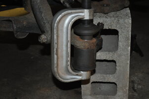
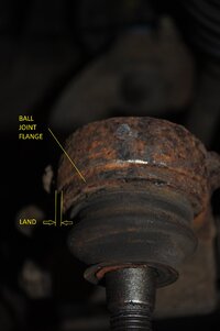
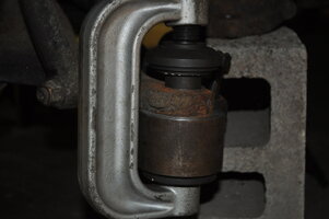
Use a hammer and cold chisel to bend the lower ball joint flared retainer flange straight.
 DSC_0021
continued
Replace 4 Ball Joints, 2 Tie Rods and 2 Stabilizer Links: Part 2
Last edited:

