- Jul 22, 2015
- 2,724
Rebuilding (sorta) the front differential – 7.25 IFS (IOP)
I haven't seen much online concerning this diff, so thought I'd put some info on it here, since we're the main users of it. I think a version of it was also used in the S10 / S15 pickups, but the case and output shaft on that one are different than ours. Some references to it will include 'IOP', which is 'In Oil Pan' (that's us).
My adventure started with the realization that the fluid had leaked out, which is actually pretty common with these. These appear to come from the factory with anaerobic sealer joining the case halves, in lieu of an actual gasket. Obviously, that solution doesn't work, so we'll find something else.
The second cause of leakage is from the outer seals. Given that the diff had to come out to reseal the case (and that my Envoy is now 20 model years old), I decided that I'd replace the seals as well, and give the internals a look-see (and I'm glad I did).
If you're pulling this out of your truck... well, get ready for a lot of work. You'll be pulling both CV axle shafts, the splined disconnect (which often is stuck to the oil pan), the intermediate shaft (in the oil pan), unbolting the diff (but not removing it), then the oil pan itself (especially if you have the V8, like I do). After all of that, the diff can be removed.
My disconnect actually came off the pan easily – it wasn't stuck at all. The differential was a different story. What worked for me was a set of pickle forks (ball joint separators), along with a few hours spent wedging them into different areas between the case and the pan. I do not recommend hammering on the ends / edges of the case, trying to break the bond between the case and the pan (like you can for the disconnect); I wound up cleaving off a 3” x 0.25 wide section of the case, doing that. Thankfully, it was on the edge, didn't affect the fluid holding capability, and I was able to use some JB Weld to reattach it.
So, we'll assume you have the diff out of the truck, and are ready to start working on it.
Before turning a bolt on the case, I highly recommend watching the following South Main Auto tutorial, to familiarize yourself with the workings of GM's front differentials used in trucks (this one is from a Tahoe, but it uses the same type of side adjusters that ours does). It's about an hour long, but it's time well spent if you're new to this. I watched it a couple of times, referring back to it when needed, as I've never set up gears before, and this diff uses adjusters vs. shims (like on rear diffs).
SMA -- rebuilding front diff / gears (Tahoe)
I'm going to split this into three parts – 'seals only', 'seals plus case', and 'seals / case / bearings'
I wound up doing all of these (except the pinion bearing, which I judged to be good). If your pinion bearing or pinion oil seal needs replacing, this write-up is not going to fully help you, and unless you have experience setting up a differential, I'd recommend having a professional set up yours, once you've torn it down. I spent a fair bit of time on adjustments, and I didn't even touch the pinion bearing.
'Seals only' (do this if you're sure your leak is only coming from here, and not from the case seam)
You'll need:
- National 710687 and 710688 seals (left / right sides, respectively)
- A seal puller (the seals are thick and rigid, and can be difficult to get out. They also function to lock the side adjusters in place).
Whatever method you prefer to drive the seal in (a seal driver kit is nice, but many people use blocks of wood, etc.)
First, match up your seals to each side of the ones installed on the diff. You'll see the one on the driver's side has a wider opening than the passenger side (which you normally can't see, as it's on the oil pan side). That's because the driver's side has the CV axle attaching to the diff, while the passenger side has the intermediate shaft attaching to it.
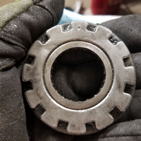
Once you get the seal off, you're going to see the side adjuster underneath it. DO NOT MOVE THESE. They shouldn't really move, with the tension of the side bearings / carrier in back of it, but consider yourself warned. I'd also replace one seal at a time, in order to ensure the adjusters stay in the position they're at. If you clean the top of the adjuster, you'll see that one of the 'tabs' has a very small diamond-shaped dimple in the center (top center in photo below). This is your reference point. If the 'wheel' of the adjuster spins freely, make sure it's in the same place when you drive the new seal in. Clean gently.

(One of the side adjusters removed. Note the dimple at the top; it'll be hard to see unless you clean the surface. Also, the press-in inner needle bearing is shown here – mine were both good)
If you turn the old seal over, you'll see a bunch of small tabs surrounding the outer edge / lip. And you'll probably see that all except two are pushed against the back of the seal. The two that still hang down are the ones that kept the side adjuster in place. (note: the SMA / Tahoe demo locks the adjuster via a separate metal tab that inserts between the adjuster and the case – that's where these two differ).
GM says you don't have to line up the tabs on the seal with the slots on the adjuster. But I'd try to make sure at least two were lined up, on opposite sides. There are 12 tabs on the adjuster, and 14 on the seal, so I guess they figure that's how two of them will not compress, and hold the adjuster in place.
Clean the housing, optionally smear a little lube on the inside edge of the case housing, and drive the seal in. Done. Up to you if you want to run some sealant on the outer edge of the case halves as 'insurance', but if it does develop a leak, don't expect that to hold too long. I would also clean, deburr, etc., the 'lip' of the passenger side of the diff that attaches to the pan, and coat it with anti-seize, in case you ever have to repeat this exercise. And, given the effort needed to get the diff out of the truck, and depending on the age / mileage... why not ensure the internals / case seal is good, as well? But if you're sure the seals were your only issue, and you're a person of faith... then go ahead and reinstall the diff.
'Seals plus case'... For this, you need all of the above parts from the last section, along with a tube of sealant. I used Permatex 'Ultra Black'; it was the best one I found at the local parts store.
Also needed: 15mm wrench / socket, torque wrench.
Pry out the oil seals as per above, keeping track of the adjuster positions. (I wouldn't put the new seals in just yet, as you may decide to 'go further', once you see the internals.) Then split the case. The ten (10) 15mm bolts that connect the housing together are all the same length, so no need to keep track of which one came from where. Put them aside for now.
Set the case so that the larger half (driver's side) is down, and the smaller half is facing up. To split the case, I didn't really have to pry much. There's a lip on the one end ('front', as it's installed on the truck) that will allow you to get a large screwdriver or pry bar in to split the case, if needed.
With the case halves separated, you'll notice that it didn't appear to have much in the way of sealant connecting the two halves. Time to clean. I used a sanding drum on a rotary tool to prep the surfaces.
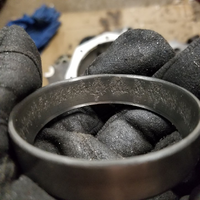
From here, it's not a problem to check the bearings. You'll be looking at the inner / passenger side. Check both the outer race (which is in the case half) and the bearing (pressed onto the carrier shaft). My outer races on both sides were pitted, so I decided to replace the bearings. More on that later. You can lift the ring gear right out of the bottom assembly and check the bearings on that end, too. Note that the outer race on this end may be very loose in the housing, and, with no tension, the side adjusters will both now move freely, if you're not careful (see: 'The ring gear...' in the next section, below).
With the carrier out, you can now inspect the following:
Carrier gears (this is an open diff, so there's no locker)
Ring gear
Pinion gear
Backlash / any noise on pinion. Basically, you want to make sure that when you spin the pinion gear, that you don't have any noise, and that the 'free movement' until the yoke starts turning the pinion is small. Also, look at the area behind the 'dust cover' (black plastic, just behind the yoke) to make sure you don't see an obvious oil leak. If you do... then it's advisable to replace the oil seal (but you have to disconnect the yoke and pinion nut to get to this, which I don't go into here, and this is where things get tricky, if you don't have experience with this).
If you're sure your bearings / gears are good, apply your sealant and reassemble the case halves per the directions on the sealant. For the Ultra Black, this means that you cover one side of the housing mount surface, including around the bolt holes, using enough so that it will 'squeeze' out of the side of the case (but it won't squeeze out until it's torqued). I wound up using approximately 1/3 of the tube. Then, place the two halves together, but only snug the bolts in (or, 'finger tight'). After one hour, then torque the bolts to spec (which is 35 ft-lb). Wait 24hrs before filling with fluid. Reassemble diff and other parts, and you're done. But if you need to replace bearings, continue on...
<End of part 1>
I haven't seen much online concerning this diff, so thought I'd put some info on it here, since we're the main users of it. I think a version of it was also used in the S10 / S15 pickups, but the case and output shaft on that one are different than ours. Some references to it will include 'IOP', which is 'In Oil Pan' (that's us).
My adventure started with the realization that the fluid had leaked out, which is actually pretty common with these. These appear to come from the factory with anaerobic sealer joining the case halves, in lieu of an actual gasket. Obviously, that solution doesn't work, so we'll find something else.
The second cause of leakage is from the outer seals. Given that the diff had to come out to reseal the case (and that my Envoy is now 20 model years old), I decided that I'd replace the seals as well, and give the internals a look-see (and I'm glad I did).
If you're pulling this out of your truck... well, get ready for a lot of work. You'll be pulling both CV axle shafts, the splined disconnect (which often is stuck to the oil pan), the intermediate shaft (in the oil pan), unbolting the diff (but not removing it), then the oil pan itself (especially if you have the V8, like I do). After all of that, the diff can be removed.
My disconnect actually came off the pan easily – it wasn't stuck at all. The differential was a different story. What worked for me was a set of pickle forks (ball joint separators), along with a few hours spent wedging them into different areas between the case and the pan. I do not recommend hammering on the ends / edges of the case, trying to break the bond between the case and the pan (like you can for the disconnect); I wound up cleaving off a 3” x 0.25 wide section of the case, doing that. Thankfully, it was on the edge, didn't affect the fluid holding capability, and I was able to use some JB Weld to reattach it.
So, we'll assume you have the diff out of the truck, and are ready to start working on it.
Before turning a bolt on the case, I highly recommend watching the following South Main Auto tutorial, to familiarize yourself with the workings of GM's front differentials used in trucks (this one is from a Tahoe, but it uses the same type of side adjusters that ours does). It's about an hour long, but it's time well spent if you're new to this. I watched it a couple of times, referring back to it when needed, as I've never set up gears before, and this diff uses adjusters vs. shims (like on rear diffs).
SMA -- rebuilding front diff / gears (Tahoe)
I'm going to split this into three parts – 'seals only', 'seals plus case', and 'seals / case / bearings'
I wound up doing all of these (except the pinion bearing, which I judged to be good). If your pinion bearing or pinion oil seal needs replacing, this write-up is not going to fully help you, and unless you have experience setting up a differential, I'd recommend having a professional set up yours, once you've torn it down. I spent a fair bit of time on adjustments, and I didn't even touch the pinion bearing.
'Seals only' (do this if you're sure your leak is only coming from here, and not from the case seam)
You'll need:
- National 710687 and 710688 seals (left / right sides, respectively)
- A seal puller (the seals are thick and rigid, and can be difficult to get out. They also function to lock the side adjusters in place).
Whatever method you prefer to drive the seal in (a seal driver kit is nice, but many people use blocks of wood, etc.)
First, match up your seals to each side of the ones installed on the diff. You'll see the one on the driver's side has a wider opening than the passenger side (which you normally can't see, as it's on the oil pan side). That's because the driver's side has the CV axle attaching to the diff, while the passenger side has the intermediate shaft attaching to it.
Once you get the seal off, you're going to see the side adjuster underneath it. DO NOT MOVE THESE. They shouldn't really move, with the tension of the side bearings / carrier in back of it, but consider yourself warned. I'd also replace one seal at a time, in order to ensure the adjusters stay in the position they're at. If you clean the top of the adjuster, you'll see that one of the 'tabs' has a very small diamond-shaped dimple in the center (top center in photo below). This is your reference point. If the 'wheel' of the adjuster spins freely, make sure it's in the same place when you drive the new seal in. Clean gently.

(One of the side adjusters removed. Note the dimple at the top; it'll be hard to see unless you clean the surface. Also, the press-in inner needle bearing is shown here – mine were both good)
If you turn the old seal over, you'll see a bunch of small tabs surrounding the outer edge / lip. And you'll probably see that all except two are pushed against the back of the seal. The two that still hang down are the ones that kept the side adjuster in place. (note: the SMA / Tahoe demo locks the adjuster via a separate metal tab that inserts between the adjuster and the case – that's where these two differ).
GM says you don't have to line up the tabs on the seal with the slots on the adjuster. But I'd try to make sure at least two were lined up, on opposite sides. There are 12 tabs on the adjuster, and 14 on the seal, so I guess they figure that's how two of them will not compress, and hold the adjuster in place.
Clean the housing, optionally smear a little lube on the inside edge of the case housing, and drive the seal in. Done. Up to you if you want to run some sealant on the outer edge of the case halves as 'insurance', but if it does develop a leak, don't expect that to hold too long. I would also clean, deburr, etc., the 'lip' of the passenger side of the diff that attaches to the pan, and coat it with anti-seize, in case you ever have to repeat this exercise. And, given the effort needed to get the diff out of the truck, and depending on the age / mileage... why not ensure the internals / case seal is good, as well? But if you're sure the seals were your only issue, and you're a person of faith... then go ahead and reinstall the diff.
'Seals plus case'... For this, you need all of the above parts from the last section, along with a tube of sealant. I used Permatex 'Ultra Black'; it was the best one I found at the local parts store.
Also needed: 15mm wrench / socket, torque wrench.
Pry out the oil seals as per above, keeping track of the adjuster positions. (I wouldn't put the new seals in just yet, as you may decide to 'go further', once you see the internals.) Then split the case. The ten (10) 15mm bolts that connect the housing together are all the same length, so no need to keep track of which one came from where. Put them aside for now.
Set the case so that the larger half (driver's side) is down, and the smaller half is facing up. To split the case, I didn't really have to pry much. There's a lip on the one end ('front', as it's installed on the truck) that will allow you to get a large screwdriver or pry bar in to split the case, if needed.
With the case halves separated, you'll notice that it didn't appear to have much in the way of sealant connecting the two halves. Time to clean. I used a sanding drum on a rotary tool to prep the surfaces.
From here, it's not a problem to check the bearings. You'll be looking at the inner / passenger side. Check both the outer race (which is in the case half) and the bearing (pressed onto the carrier shaft). My outer races on both sides were pitted, so I decided to replace the bearings. More on that later. You can lift the ring gear right out of the bottom assembly and check the bearings on that end, too. Note that the outer race on this end may be very loose in the housing, and, with no tension, the side adjusters will both now move freely, if you're not careful (see: 'The ring gear...' in the next section, below).
With the carrier out, you can now inspect the following:
Carrier gears (this is an open diff, so there's no locker)
Ring gear
Pinion gear
Backlash / any noise on pinion. Basically, you want to make sure that when you spin the pinion gear, that you don't have any noise, and that the 'free movement' until the yoke starts turning the pinion is small. Also, look at the area behind the 'dust cover' (black plastic, just behind the yoke) to make sure you don't see an obvious oil leak. If you do... then it's advisable to replace the oil seal (but you have to disconnect the yoke and pinion nut to get to this, which I don't go into here, and this is where things get tricky, if you don't have experience with this).
If you're sure your bearings / gears are good, apply your sealant and reassemble the case halves per the directions on the sealant. For the Ultra Black, this means that you cover one side of the housing mount surface, including around the bolt holes, using enough so that it will 'squeeze' out of the side of the case (but it won't squeeze out until it's torqued). I wound up using approximately 1/3 of the tube. Then, place the two halves together, but only snug the bolts in (or, 'finger tight'). After one hour, then torque the bolts to spec (which is 35 ft-lb). Wait 24hrs before filling with fluid. Reassemble diff and other parts, and you're done. But if you need to replace bearings, continue on...
<End of part 1>


