P10 PCM 5 Volt References

TJBaker57

Original poster
Member
Aug 16, 2015
2,900
Colorado
Not sure where this would be best so will park it here.

I have recently grabbed a couple of P10 PCMs from the junkyards. I have just completed fully checking the resistance to ground of each and every pin from all 3 connectors of the 2 units and have entered the data in spreadsheet. I intend to recheck these values with a better quality meter at some point.

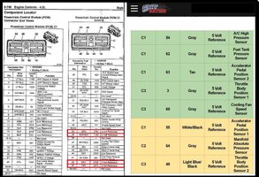
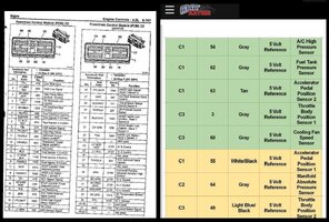
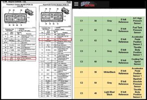
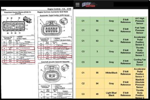
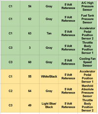
While doing this it occurred to me to see what I could learn about the 5 volt reference circuits. I checked continuity between all the 5 volt reference circuits and grouped them in a table, colored by grouping which I will post here. I also stumbled upon an additional 3 pins that present one of the two 5 volt references but are not used. These are all on connector 2, pins 53, 56, and 63. They share the circuit of C1-54.

Screenshot_20201002-161741~01.png
 

mrrsm

Lifetime VIP Donor
Supporting Donor
Member
Oct 22, 2015
7,700
Tampa Bay Area
The best I could do in order to understand the context here... was to place your Color Coded Table next to each of the Three PCM Connector Pin-Outs, with the 5 Volts DC Reference Pins Highlighted in Red:
5VOLTREFSPINOUTC1.jpg5VOLTREFSPINOUTC2A.jpg5VOLTREFSPINOUTC2B.jpg5VOLTREFSPINOUTC3.jpg
 

TJBaker57

Original poster
Member
Aug 16, 2015
2,900
Colorado
The best I could do in order to understand the context here... was to place your Color Coded Table next to each of the Three PCM Connector Pin-Outs, with the 5 Volts DC Reference Pins Highlighted in Red:
View attachment 97654View attachment 97655View attachment 97656View attachment 97657


Well that seems good!! I was not sure my initial explanation and table was sufficient. With a PCM on the kitchen table I tested for continuity between a given 5 volt reference pin and all other pins. This would mean that those pins with continuity between them must share a 5 volt reference power supply inside the PCM.

What I noted straight away was that the MAP sensor and the Fan Clutch do not share a 5 volt reference and so disconnecting the Fan Clutch when one has a MAP sensor issue should at least in theory accomplish absolutely nothing.

Edit: I also wondered why they didn't distribute the load more evenly across the two 5 volt circuits. They put 5 sensors on one circuit and just 3 on the other.
 
  • Like
Reactions: mrrsm

Mooseman

Moderator
Dec 4, 2011
25,324
Ottawa, ON
And also shared the one between the fan and throttle sensor. You would think that such an essential system, the throttle system would have been on its own.
 

mrrsm

Lifetime VIP Donor
Supporting Donor
Member
Oct 22, 2015
7,700
Tampa Bay Area
The answer to THAT Puzzle may be that General Motors Throttle Body Control System, The MAF System and The ACC Pedal System Must ALL be Kept "Tied Together and Weakened" Due to the Safety Considerations placed upon the PCM to immediately Default to a "Reduced Power" or immediately Default to a "Limp Mode" status at any time when the AIR Intake cannot be controlled and shut off down to a Safe "Idle" Status.

Don't Kid yourself... GM LOST MILLIONS in settling Wrongful Death Law Suits because their Original PCM-Throttle Body-Gas Pedal Hardware and PCM Programming and Throttle-Intake Control Design were flawed enough to allow "Runaway Engine Conditions" to occur on a number of occasions that lead to Out Of Control, Unstoppable Vehicles involved in Fatal Accidents.

My 'Best Guess' about their re-design making the Throttle Air Control Circuit is because this entire set up is strictly a matter of having an "Air Management Design" and NOT a "Fuel Management Design" ...which many people might not believe to be the case of all GM PCM-ECM Engine Control Management Designs.
 

Mooseman

Moderator
Dec 4, 2011
25,324
Ottawa, ON
I get that but my beef is that it was also tied to the unrelated fan clutch which can be addressed with a simple OBD code allowing the engine to work normally.
 
  • Like
Reactions: gmcman and mrrsm

TJBaker57

Original poster
Member
Aug 16, 2015
2,900
Colorado
I checked out a P12 PCM from a 2006 yesterday and found the grouping of sensors sharing a 5 volt reference the same as the P10 grouping with the addition of the SAIS pressure sensor. Again the load seems unbalanced, perhaps even more so with the addition of the SAIS sensor.

APP#1, TPS#2 and MAP are grouped together on one 5 volt reference and all other sensors are on the other 5 volt reference. These being APP#2, TPS#1, A/C High Pressure, Cooling Fan Speed, SAIS pressure, and Fuel Tank Vapor Pressure.

I took a look at the "Low Reference" terminals as well wondering if these were also grouped. If memory serves they were all grouped together having continuity amongst them all.

I noted a few terminals that are labelled as "Low Reference" in wiring diagrams do not appear to actually be a low reference at all. One wire each from the crankshaft position sensor, and the two knock sensors are labelled as low reference in wiring diagrams but measure a high resistance to ground. And both terminals to the CKP sensor measure the same resistance to ground while unpowered and a negative voltage to ground when powered up. How curious.
 
  • Like
Reactions: Mooseman and mrrsm

mrrsm

Lifetime VIP Donor
Supporting Donor
Member
Oct 22, 2015
7,700
Tampa Bay Area
The possible explanations are:

(1) The CKP "Crankshaft Sensor" is NOT a True "Sensor"...in the Strictest 'Sense' of that Word. Rather, it is a highly reliable Electro-Magnetic Induction Device (originally conceived by Michael Faraday) having a very fine, Wire Wound Coil wrapped around a Permanent Magnet. This unit creates a Mild, Alternating Current Field (A/C) producing a Sine Wave by the passage in close proximity with the 60 (-2) Steel Teeth evenly cut into the OD of the rotating Crankshaft 58 Tooth Reluctor Ring in the Late Model GMT360s.

The Vacant (-2) Teeth Spacing in the OD of the Reluctor Wheel provides an Arbitrary Break in the Cycle necessary to coincide with Top Dead Center of the #1 Cylinder during 720 Degrees of Crankshaft Rotation. Therefore, each Reluctor "Tooth" represents a predictable 6 Degrees of Motion of the Crankshaft rotating within a full 360 Degree Circle.

Consequently, the CKP Device does not require a 5 Volt Reference Signal in the same manner that a Hall Effect Sensor would in order to perform its function. In some vehicles, there is a Separate Module included in the Engine Management System that interfaces with, interprets and converts the CKP A/C Sine Wave over to a Hall Effect Signal in order to make it easier for the PCM-ECM to make its 'mechanical positional comparison checks' between where the Crankshaft and Camshaft(s) are at all times using the input from the CPS Exhaust Camshaft Position Hall Effect Sensor as "The Foil".

This fallible predictability helps to determine whether or not Proper Ignition Timing - Spark Plug Firing and EFI Pulsing are all behaving and doing their parts when all of these events are truly in their correct, relative positions within the 720 Degree, Four Stroke Combustion Cycle. Conversely, they also serve to point out the irreconcilable differences that can happen when Mechanical Failures are developing in High Mileage Motors with Worn Timing Chains, Over-Extended Timing Chain Tensioners and Worn-In Grooved Plastic-Nylon Timing Chain Guides.

(2) Likewise, rather than being "True Sensors"... the Two Knock Sensors are actually "Piezoelectric" Devices that rely upon Engine Vibrations "In Excess" to generate Mild Electrical Signals by the simple action of the Bending or Flexing of its Crystal Substrate. This phenomena only occurs when the Motor shakes with sufficient violence from 'Engine Knocks' to bend and flex the minute, suspended Crystals inside of their 'Hollow Chambers'.

Such events will cause the Crystals to generate Minute Electrical Currents that can be picked up by the PCM after a certain number of these events occur over a set time frame. Whether the PCM deems this a problem or not is dependent upon BOTH Knock Sensors signalling their cascade to the PCM, allowing it to help interpret problems such as "Poor Quality or Low Octane Fuel, Pre-Ignition events from a Damaged Spark Plug, Excessive Compression from having Incorrect Head Gasket 'Quench' or Incorrect Piston Height in Turbo-Charged Applications. Thus... they can help determine these conditions and No 5 Volt DC Reference Signal is actually necessary for them to 'work'.
 
Last edited:
  • Like
Reactions: budwich

Forum Statistics

Threads
23,314
Posts
637,846
Members
18,520
Latest member
Firebaugh86

Members Online

No members online now.