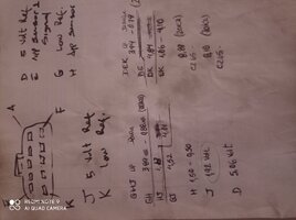
So today I made this little graphic up so I would have what I needed without scrolling around in the 2002 wiring diagram...
View attachment 101371
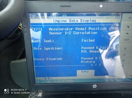
I probed the PCM C1 connector to read the two APP sensor voltages and observed these while moving the pedal and also watched the PIDs for these sensor outputs in Torque Pro. For 2002 the PIDs are 1478 and 1479. I have no way of knowing if they are the same for later years.
I learned that the PIDs as displayed in the Tech2 as well as any app like Torque Pro are not the raw values. The Pids appear to be massaged into a stable reading while the actual sensor voltages fluctuate slightly. Not surprising really.
Besides that news about the PIDs not being raw values the voltages were seen to rise and fall as expected in response to pedal movements. I also checked the 5 volt references and they were stable. I moved on to resistance tests of the pedal sensor.
I disconnected the PCM C1 connector and used a probe set to make connections to my multimeter(s). Here I began with reading the full resistances seen by the 5 volt circuits of C1:63 to C1:11 for APP sensor #2 and C1:55 to C1:10 for APP sensor #1. Rounding to a single decimal there was about a 200 ohm difference between the two, one was at 4.5k and the other was 4.3k. I verified there were no fluctuations with pedal movement, as expected.
Reading resistances from each sensor output, C1:1 or C1:2, to either the 5 volt terminals, C1;63 or C1:55, or the low reference terminals, C1:11 or C1:10, I observed all the expected variances with pedal movements.
It bears stating that this vehicle has never during my ownership of over ten years had a reduced engine power condition or accelerator position or throttle position error.

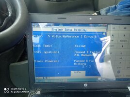


 which requires reprogramming. Question: why was it C3 60 5v ref a short to ground fanclutch the rest of the sensors linked to the 5v source were fine except for the 5v of the acceleration pedal? I was left with the doubt friends.
 and it remains to test that the box makes the changes.