How To Use PICO #2204A & HANTEK #1008C Oscilloscopes

mrrsm

Original poster
Lifetime VIP Donor
Supporting Donor
Member
Oct 22, 2015
7,705
Tampa Bay Area
Last edited:

mrrsm

Original poster
Lifetime VIP Donor
Supporting Donor
Member
Oct 22, 2015
7,705
Tampa Bay Area
Late this Afternoon... and Two Days Early... The Autel Maxi-Scope Gear arrived from eBay. But what was SO COOL about this "Get" was what happened AFTER I found the Sale Price (Minus $200.00 off the OEM Price because of an "Open Box" condition...??? WTF.. It has NEVER even Been Opened!) ) and lucked into grabbing this Brand New, Pristine "Autel Oscilloscope Kit"...was finding a Carry Case for this Stuff... ALSO made by AUTEL.

WHAT?!!! Are You KIDDING Me?
And I mean like ALL of this Surprisingly HEAVY Oscilloscope Rigging fits PERFECTLY Inside of it, too??? Yeah!!! Apparently this Bag was actually designed to Protect and Carry an Autel Robotics Division Helo-Drone.

But I'm guessing that this Bag was recently 'dumped off' over on eBay by some P*ssed Off Dad for under $30.00... just after his Kid let his Best Drone Batteries run too far down and he Lost "The Bird" it used to carry somewhere way the Hell Out in the Woods. Or maybe he let it wander too far out off shore over the Ocean somewhere while he was at the Beach.

Anyways... RIP Autel Robot Helo-Drone...

Because NOW ...this Brand New Black Nylon Autel Bag starts out on its Re-Purposed Journey in Life ...and it STILL gets to carry its Corporate Autel LOGO on The Very Excellent Goodies it cradles inside that it was Destined to Protect all along. Pretty Cool & Amazing Story!!!

That said, Here are the "Un-Boxing" Images and tomorrow I'll follow up with installing the Autel Maxi-Scope Software onto my RCA Cambio II Windows 10 (32 Bit) Tablet... and maybe try some interesting things out. :>)


MAXISCOPEUNBOX1.jpgMAXISCOPEUNBOX2.jpgMAXISCOPEUNBOX3.jpgMAXISCOPEUNBOX4.jpgMAXISCOPEUNBOX5.jpgMAXISCOPEUNBOX6.jpgMAXISCOPEUNBOX7.jpgMAXISCOPEUNBOX8.jpgMAXISCOPEUNBOX9.jpgMAXISCOPEUNBOX10.jpgMAXISCOPEUNBOX11.jpgMAXISCOPEUNBOX12.jpgMAXISCOPEUNBOX14.jpgMAXISCOPEUNBOX15.jpgMAXISCOPEUNBOX16.jpgMAXISCOPEUNBOX17.jpgMAXISCOPEUNBOX18.jpgMAXISCOPEUNBOX19.jpgMAXISCOPEUNBOX20.jpg
 
  • Love
Reactions: azswiss

mrrsm

Original poster
Lifetime VIP Donor
Supporting Donor
Member
Oct 22, 2015
7,705
Tampa Bay Area
I forgot to mention that even after (Comfortably) STUFFING ALL of that Autel MAXI-Scope Gear into the Little Autel Robotics Bag, I STILL have JUST Enough Room to ensconce my other Hantek Model #2D82-AUTO Oscilloscope inside!

How Cool is THIS?

AUTELCARRYBAG2.jpgAUTELCARRYBAG3.jpgAUTELCARRYBAG6.jpgAUTELCARRYBAG5.jpgAUTELCARRYBAG4.jpg

And because of the Commonality of the BNC Connectors AND the 4mm Banana Probes and Leads in this Kit... If I need to Diagnose something "Quick & Dirty" where I only require (2) Channels for the Diagnostic and the use any of the 80 Built-in Automotive Diagnostic Tests in the Hand-Held (3) Hour Endurance Battery Powered Hantek "Black Brick" ... I can use IT instead of having to "GO YARD" with a complete set up of the 4 Channel Autel MAXI-Scope along with a requisite Laptop or Tablet Computer. SO-IT'S-SNUG-AS-A-BUG ...and ...I LIKE IT!

I also wanted to make mention that if you've watched any of Eric "O"s PICO-Scope Videos of him working away at South Main Auto (SMA) up in Avica, New York, then you've seen him venturing FROM the Work Vehicle ...over TO his "Bench Top Area" on the Two Garbage Cans in the corner of the Shop in order to have enough room to open up and spread out his CAVERNOUS PICO-Scope Carry Case and fish out whatever he required in the way of the various Current Clamps, Point Probes & Leads to do those Jobs:

SMAOSCILLOSCOPE1.jpgSMAOSCILLOSCOPE2.jpgSMAOSCILLOSCOPE3.jpgSMAOSCILLOSCOPE4.jpgSMAOSCILLOSCOPE5.jpg

But for the REST of Us who may have to do our Diagnostic Work in someone's Drive Way (at a very inconvenient hour) and while we're are sitting inside the Cab of someone's Disabled SUV... Having all of this Gear inside such a Nice & Tidy Autel Robotics 'Ditch & Don' Oscilloscope Carry Bag is just about as HANDY as it gets! :>) So... I LIKE IT!

Let me finish out this Post with some Cool Video Training Installments showing How To Hook Up and Set Up the Autel MAXI-Scope Gear with a Low Amperage Current Clamp whenever Diagnosing Suspected Fuel Pumps.

MOST of the Time... Fuel Pumps Do NOT Suddenly Fail... but gradually diminish in their Fuel Pressure Delivery and Performance because there may components inside of them like those with Copper Commutators that can actually wear down inside of Brush-Type Fuel Pumps.

This Style of Electric Fuel Pump can eventually present with inconsistent Current Clamp Captured Wave Forms as described on the Oscilloscope Screens shown below.

These Visual Instructions should Help to de-mystify:

'How Do I Set Up All This Oscilloscope Gear to Test Fuel Pumps on Running Cars & Trucks?'

...and give everyone the confidence and encouragement necessary for them to want to Use this Diagnostic Testing Equipment along with their Other Tools on a Regular Basis.

Please... Play these Training Sessions at 1/2 to 3/4 of the Normal Speed, as this Instructor Speaks at a VERY Rapid Pace and his Dialogues are always VERY DENSELY PACKED with Good Information:


Last edited:

mrrsm

Original poster
Lifetime VIP Donor
Supporting Donor
Member
Oct 22, 2015
7,705
Tampa Bay Area
Okay... THIS is Weird... But it's Actually 'Pretty Effing Cool' and VERY INTERESTING, Too:

So I saw THIS Noise Master Vibration Sensing Kit that focuses with the Mechanic using Two of his Five Senses via his Vision and Hearing while analyzing the (6) Inputs from some Clamp On Microphones sporting the typical 3.5mm Audio Jacks.

These (6) "Sound Clamps" get attached to a set of(6)n Extra Long Wired Leads meant to Plug into the Base of the Device AKA "The Noise Master" meant to Diagnose Errant Automotive Vibrations from the Engine, Transmission, Body or Suspension.

Okay... So Far ...So Cool... Right? Okay, So In and of itself THIS Diagnostic Audio Tool Kit (as shown below in these Un-Boxing Images) really is an Excellent Bargain offered over on Amazon for only $90.00 via THIS Link:

CHASSISEAR.jpgNOISEMASTER1.jpgNOISEMASTER2.jpgNOISEMASTER3.jpgNOISEMASTER4.jpgNOISEMASTER6.jpg

But...Then I started thinking... with @Mooseman 's Voice inside my Head making observations... while asking me:

"Yeah, Bobby... That's Okay... I Suppose..."

"But ...What if I want to Know EXACTLY What the Frequencies and Amplitudes of those Automotive Sounds are and NOT just Graduated Variations of Color, Motions & Sounds?"

"Have you got anything in that "Audio Grab Bag" that will meet with our 'Non-Five Senses' and still be able to show me THAT Information...?"

So after thinking about 'His' Question for a minute... I was like... "BINGO!" And I blurted out to no one in particular:

"OH, HELL YEAH!!!"


It occurred to me that all of those Six (6) Copper, Spring Loaded "Mike Clamps" with their Standard Female 3.5mm Audio Jack Leads would need for any Oscilloscope Analysis is either using (6) of THESE BNC Male to Male 3.5mm Audio Jack Adapters:

BNCTO35MMAUDIO1.jpg

...or get (6) of THESE as Complete, Shielded Cable Units for a Whole LOT More Moolah:
BNCTO35MMAUDIO.jpg

...and then I can (Test Out) using those (6) Copper Microphone Clamps via either Hantek, Pico or Autel Software Suites after setting up a "Custom Audio Probe" within the 'Guess Ranges' for their Various Automotive Vibration Frequencies and Amplitudes ... Perhaps much Easier Said...than ...Done.

Then by using a separate BNC Channel on the Oscilloscope for reading TDC Cylinder #1 for an RPM reference... I'd be able to Read, Time and Calculate the Frequency and Amplitude of ANYTHING THAT SHAKES in between any One or ALL Six of those very same "Sound Master" Copper Microphone Clamps with a Pretty High Sampling Rate and Precision.

Man... Talk about "Getting the MOST Out of YOUR Tools...."


Well Damn... DON'T YOU JUST LOVE THIS STUFF...?!!!

So... Thanks for being "The Muse" on this, @Mooseman !

Anyway... I know this is NOT an 'Earth-Shattering Repair Revelation', so whenever Time Permits... I'm going to have to work on this idea a bit more and then Experiment and Post Up the Honest, Accurate Test Results here afterwards. I've gotta say... I'm fairly exited about the possibilities that are here. :>)
 

Attachments

  • NOISEMASTER5.jpg
    NOISEMASTER5.jpg
    101.1 KB · Views: 0
Last edited:

mrrsm

Original poster
Lifetime VIP Donor
Supporting Donor
Member
Oct 22, 2015
7,705
Tampa Bay Area
Hmmm… Okay… If I’m going to get grounded in a better understanding of what is possible with using an Oscilloscope for Sound Analytics… then it’s Time to Go To School and attend the Official PICO-Scope Course Classes on The Study of Automotive NVH...

NVH?

(1) Noise
(2) Vibration
(3) Harshness

PICO-Scope Introduction to NVH:

https://www.picoauto.com/library/videos-nvh


...and here are the remaining PICO-Scope NVH Follow On Courses available via THIS Link:

https://www.picoauto.com/library/videos-nvh
 

mrrsm

Original poster
Lifetime VIP Donor
Supporting Donor
Member
Oct 22, 2015
7,705
Tampa Bay Area
More Good News on this subject comes from Sean Boyle from SIU Automotive College via his YouTube Channel:

https://www.youtube.com/c/siuautomotive

For anyone who will NOT be Dropping $1,200.00 on a Professional NVH Diagnostic PICO-Scope Noise and Vibration Analysis Kit as described in the above NVA Training Videos:

Make your own Vibration Analyzer for 20 bucks! In this video I show you how to make a Vibration Analyzer to use with your Scope and I provide some examples of it in use. In one of my classes, I have students make these sensors to use with their Pico 2204A scope so they can measure and calculate vibrations.

The concept is similar to the expensive vibration analyzers, but this process requires the user (you) to do all the calculations. But that's a good thing! If you're learning, you're best off knowing how the fancy expensive machines figure out the problem.

This vibration analyzer can easily be used to measure wheel/tire related vibrations, drive-line vibrations, engine/accessory vibrations. It can even pick up engine misfires.

You might say that you can download an app for your phone, like "vibrations!" (android) and get the same data. This is true and that app is great, but you'll see in this video you can also build and utilize a position sensor so you can Sync the Vibration to a Component Position. With that information, you will know where to place weight if you intend on fixing the imbalance.”


Parts List:

From AdaFruit.com
Accelerometer - ADXL335
IR sensor (here or digikey below) - ITR20001/T

From digikey.com
IR sensor (here or adafruit above) - QRD1114
10k Ohms resistor - CF14JT10K0
470 Oms resistor - CF14JT470R
5v regulator – L7805CV


Perhaps @TJBaker57 has already built and tested his own variation on these inexpensive Accelerometers and would share his Component Breadboard Design with us…

Here Sean shows us how he builds Inexpensive Pressure Pulse Sensors with a wide range of uses when taking and Diagnosing Automotive Pulsing Measurements using Piezo-Electric Devices outputs to the PICO-Scope Software:

 
  • Like
Reactions: budwich and azswiss

mrrsm

Original poster
Lifetime VIP Donor
Supporting Donor
Member
Oct 22, 2015
7,705
Tampa Bay Area
One of the things I've been meaning to 'add to the fray' around this Topic has been obtaining the inexpensive means to be able to 'practice' with our various Oscilloscopes in a Bench Top - Laptop Setting.

What follows on will allow any of our Folks interested in getting comfortable with the look and feel of this instrumentation... Without having to work on a "LIVE" Vehicle under what could be nerve-wracking experiences when using and seeing this Oscilloscope Gear In Action for the first few times.

To that end... Nothing could help us more than having an inexpensive 5 Volt DC Powered Digital Signal (Function) Generator providing a variety of Wave Forms and Patterns coming out of THIS Device and getting displayed On Screen using their Autel, Hantek or PICO-Scope Software:

SIGNALGENERATOR1.jpgSIGNALGENERATOR2.jpgSIGNALGENERATOR3.jpgSIGNALGENERATOR4.jpg

These Videos come from YouTube Scope Users generously providing insights into How to Use The FG-100 DDS Function Generator to Practice with Their Oscilloscopes:


For more intimate Electronic Component Scope Diagnostics:

Using Your Oscilloscope and Function Generator to Test Capacitance:

Using Your Oscilloscope and Function Generator to Measure Inductance:
https://www.youtube.com/watch?v=iQQe8uSZ8xc

For Fans of Arduino Devices...

THIS FG-100 SIG-GEN has an ATMEL EPROM Chip 'On Board' that lately is being experimented with by way of some 'Home Grown Firmware Upgrades' . THIS looks like it would make an interesting project, too:

Alternative Firmware Load for the FG-100 DDS Sig-Gen:

 
Last edited:

mrrsm

Original poster
Lifetime VIP Donor
Supporting Donor
Member
Oct 22, 2015
7,705
Tampa Bay Area
Now while I’ve recently “Done MY Bit!” with Going a Little Overboard while investigating issues with Unwanted Vibrations and Sounds for Automotive Diagnostics by:

(1) Doing the Technical Research on the Subject Matter.

(2) Spending the Necessary BREAD on the Hardware & Gear.

(3) Testing and Using this Equipment to Learn More about the Subject.

...
it does NOT follow that others NOT as interested in delving deeper into the Science and Automotive Analytics involved as much as they are in Just Getting To The Solutions should suffer.

So in brief… Check out THESE Sources for Alternatives to obtaining and using High Tech Vibration Analyzers and Oscilloscopes until after you learn a bit more about these problems and how to use a Non-FREE Cell Phone APP for this task. Then you can decide on whether or not to perform your OWN Exotic Diagnostics with the more sophisticated hardware:

NHTSA Vibration Analysis Training PDF

https://static.nhtsa.gov/odi/tsbs/2018/MC-10158122-9999.pdf

In this example, a Very Clever Dude demonstrates his creation and of an Arduino Board and a Blue Tooth Transceiver in a ‘Work Made Remote Device’ to Analyze and Graph a Very Bad Bearing in a 40,000 CFPM Electric Fan:

Used an Arduino UNO board, ADXL accelerometer, and a serial bluetooth adapter. Arduino program simply prints data from X Y and Z axis to the serial bluetooth adapter, then I import that data into windows via RealTerm software."

"I then use KST graphing software for the scope and FFT graphing. Both programs are free for windows. RealTerm writes to a windows notepad file that KST graphs the data from.”


Obviously this will never compare to the amount of precision data that legitimate vibration analysis equipment can provide, but I just wanted to show everyone what a 5 dollar board can do if you put your mind to it! "

"The FFT portion of the graph is extremely useful for seeing vibration amplitude at different frequencies. With that type of info you can factor in your RPM of equipment and actually figure out where your issue is (i.e. a bearing with 30 rollers will take x amount of RPMs on the shaft to fully rotate, so if you have a bad roller in the bearing the frequency it vibrates at will be way different than your shaft RPM).... Enjoy and thanks for watching.”


And a decent Rundown of the Various Types of Vibrations and their requisite Sensors:


The Vibration Software Site:

https://vibratesoftware.com/

The NVA App Software Video Demonstrations:


Meanwhile… Since I’ve Taken The Plunge into figuring all of this out… I’ve still got a LOT MORE to Cover on this Topic and its Unique Hardware, so...

= /Stay Vibrational/=

And as I complete more items on my list, I’ll post up the New Material as things develop... AND I WILL Be Using Oscilloscopes again for these Investigations.


DISCLAIMER:

I am neither connected with any Organization, Business or Group or Individual, nor do I benefit in any way from the Sales of ANYTHING being offered or sold or covered in Links mentioned within this Thread.
 

808

Member
May 5, 2022
209
Georgia
@mrrsm !!!! Good Sir!!!! Thank You AGAIN For Your Thorough Due Diligence!!!
Now I know "Eric "O"" Is Mr. South Main Auto!!!!!!!!"
I cannot thank you enough for linking this exceptional thread of yours to me!!!

I never did complete a fullness of review of your fantastic breadth of work here,
as I am -still on the engine stand- presently, but your assessment & reference
to the EXACT CASE STUDY in question that I just dove into today is a -major-
WOW :biggrin: hahaha!!!! EXCELLENT INSTINCTS SIR!!!!!!! THANK YOU!!!!!!!!!
 

mrrsm

Original poster
Lifetime VIP Donor
Supporting Donor
Member
Oct 22, 2015
7,705
Tampa Bay Area

How Many Of Us WOULD have Been Straight “A” Students if our Teachers had only recorded all their School Sessions? Had they done so like THIS Dude has who Teaches in a VERY Professional Manner… Our abilities to learn would have been Off The Charts. Since these Videos are quite Technical and are BEST if Watched 2-3 Times while being played at One Half Speed to help with picking up The BEST Oscilloscope User Techniques:


Relative Compression Test with a Scope [PicoScope, Autel MP408, Micsig, & Autel Ultra]


Performing a Relative Compression Test WITHOUT using an Amp Clamp:


ASE A-8 Engine Performance Test Prep [2022]


ASE A8 Practice Test [Live Class]


  • Like
  • Wow
Reactions: 808 and azswiss

mrrsm

Original poster
Lifetime VIP Donor
Supporting Donor
Member
Oct 22, 2015
7,705
Tampa Bay Area
This Post is just a bit of a sidebar to the general topic of Using Oscilloscopes, but it speaks to sense of the Pride and Accomplishment we can all feel when we conquer our fears of using this fairly technical equipment ...that does indeed have a bit of a "Learning Curve".

A while back, over in the 'What Are You Doing Today?" Thread... I posted a mention discovering a Rare, Low Dollar Sale on ebay of a Brand New "Snap-On Modis" Black Base Ball Cap that sported Red Piping on the Bill along with the "Snap-On" Logo and it had the typical appearance of the On-Screen Oscilloscope "Voltage Over Time" (Heart Beat) Traces in an attractive motif woven in Multi-Colored Thread.

So anyways... I grabbed it as a "Snap-On Nostalgic Collectible' for one reason...and also because that I think by now...I have put in the "Study Time" along with purchasing and USING the Diagnostic Equipment necessary for us all to become at minimum... Fairly Decent Automotive Diagnosticians. In other word... If I wanted to... One Day...I can Wear That Hat.and not feel the least bit squeamish about it.

It is also no secret to those of us in this industry; both Professionals and Non-Pros alike, that with a little effort and encouragement, we CAN learn enough and perform enough correct diagnostics well enough to very efficiently get under the skin of WHY Computer Managed Automotive Systems fail... and perhaps demand a deeper understanding FIRST and move us on towards becoming Better Mechanics by actually being able to understand and use these tools.

Well, with all that said... recently I was (once again) Haunting The Halls of eBay looking over one type of tool or another... and for right around $20.00... I spied THIS Very Cool Item bearing the Snap-On Logo and emulating that same oscilloscope trace motif of a Secondary Ignition Wave Form:

SNAPONFLAREPIN2.jpgSNAPONFLAREPIN3.jpgSNAPONFLAREPIN5.jpgSNAPONMODISHATWITHFLAREPIN0.jpgSNAPONMODISHATWITHFLAREPIN1.jpgSNAPONMODISHATWITHFLAREPIN2.jpgSNAPONMODISHATWITHFLAREPIN3.jpgSNAPONMODISHATWITHFLAREPIN4.jpgSNAPONMODISHATWITHFLAREPIN5.jpg

If you've ever seen "The Office" (The Movie... NOT the TV Series...) then you'll remember that Restaurant scene where the Overly-Enthusiastic "Rah-Rah" Dude brags about 'Wearing and Adding NEW FLARE" to his Employee's Vest in a very cringe-worthy way. I would never want to become THAT Guy, so I won't be wearing this Cap as matter of course. But I am like everyone else here... An Older Traveler ...Still Hoping that ONE Day... I'll be good enough to be considered worthy of wearing this Snap-On Gear ...and 'Walk In The Tall Corn ...With The Big Dogs...' :>)

Here is a Video of a VERY Talented Diagnostician ruminating over an ORIGINAL Red Snap-On Counselor Professional Automotive Diagnostic Oscilloscope called a... Wait For It... "The Counselor" . THIS Machine is STILL finding itself useful in his shop when it comes to Tuning Older Vehicles that use "Points, Plugs & Condensers", etc. His request of course would be for PICO-Scope to create some of the 'Old School Features' that make using their equipment and Software Suite so much easier. THIS Machine Sports unique capabilities that he actually demonstrates below for the consideration of the PICO-Scope Software Writers to Add into their PICO-Scope Automotive Software and all of us YouTube Viewers.

 
Last edited:

mrrsm

Original poster
Lifetime VIP Donor
Supporting Donor
Member
Oct 22, 2015
7,705
Tampa Bay Area
In the realm of "You CANNOT Get Enough Information about Using Oscilloscopes..." comes the necessity to stress that there are perhaps THOUSANDS of Automotive Oscilloscopes lying pavilion on the shelves gathering dust in Automotive Repair Shops world wide after getting such equipment. The reason for this involves the need (or lack) of many Mechanics in making a Reasonable Amount of Effort to Learn and PRACTICE using this kind of Diagnostic Equipment:


On more than one occasion, @Mooseman has suggested to us all that before we just "Dive Under the Hood" and start looking for trouble... TO BEGIN by conducting a Relative Compression Test and/or using Analog Cylinder Leak Down Equipment as a follow up procedure. The reason this makes so much sense is that, right off the bat...You can eliminate the possibility of having any Top End Mechanical Problems before attacking the requisite "Fuel, Air and Spark" as the Bare Necessities for a properly running engine. "GOT P0300...?"

I'm in complete agreement with this approach... But if one uses a 2 Channel Oscilloscope, a High Amp Clamp connected around the Battery Ground Cable (or use a Low Amp Clamp and Fuse Buddy Loop at the Fuse Box) along with a High Voltage Pick Up reading the #1 Cylinder Coil Wire (or use a Paddle Probe on the GM 4.2L COP at the #1 Cylinder) on Channel (2). you can Identify WHICH Offending Cylinder(s) are suffering with Bad Valves by following the Engine Firing Order on Screen ... THIS Alternative Method is Entirely Non-Intrusive and desirable because it is a VERY FAST METHOD FOR THE INITIAL DIAGNOSTICS.

Should suspicious problems be discovered along the way, the follow up actions WOULD include a Cylinder Leak Down Test, checking upon whether the Escaping Air was coming back Through the Intake Throttle Body (Bad Intake Valve) or Escaping from the Tail Pipe (Bad Exhaust Valve) or if the air escapes from the Crank-Case through the Dip-Stick Tube indicating (Bad Rings).

But back to the idea of Practice and Training... How can we simplify this without actually having to "Dive Under The Hood' at ALL?


Over the years, Snap-On developed Oscilloscope (and Graphing Multi-Meter) Training Auto Sensor Simulation Boards for Automotive Technical Schools and Private Repair Shops to employ in a Bench Top Setting. The two most recent versions that were available (but getting damned near non-existent) are shown below:

Snap On SUPER RARE scope demo board waveform generator. BMW 328I N52KP EESX306SP:


s-l1600FFF.jpgs-l1600EEE.jpgs-l1600DDD.jpgs-l1600CCC.jpgs-l1600BBB.jpgs-l1600AAA.jpgs-l1600.jpg

... and then there is THIS One...Also on the Brink of Extinction:

Snap-On Tools SPP816 Vantage Waveform Demo Board as described in THIS Video:


EESX306A.jpgHANTEKWITHSNAPONSIMULATOR9.jpgHANTEKWITHSNAPONSIMULATOR8.jpg
HANTEKWITHSNAPONSIMULATOR4.jpgHANTEKWITHSNAPONSIMULATOR7.jpg


I picked up one of the Last Two Available on eBay recently and then I put it through its "Bench Top Paces" to practice with it using my MOST convenient Oscilloscope:

The Hantek Hand- Held "Brick" Unit Model# 2D82:


It is Very Cool to be able to set up the Scope to test Variable Frequency, Voltage , EFI Wave Form Examples...AND Introduce *Glitches* to help learn what to LOOK for in failing or misbehaving components.

UPDATE:

The Seller, who I suspect is THIS person. "Mike, The Disgruntled Mechanic", the VOP (Video Original Poster) in the Video shown below, agreed to Drop the Asking Price by $50.00 ...So I Pulled Finally The Pin:


SNAPOWAVEFORMTRAINER.jpg
SNAPOWAVEFORMTRAINER2.jpg

...and while Snap-On would of course want to induce Auto Repair Shops and Automotive Training Schools to designate their own Scan Tools with Oscilloscope capabilities... ANY Oscilloscope WILL be able to pick up the Output Wave Forms from this or any other similar device. This Video is another Bench Top Trainer Demo In Action:


Attachments

  • HANTEKWITHSNAPONSIMULATOR5.jpg
    HANTEKWITHSNAPONSIMULATOR5.jpg
    490.7 KB · Views: 2
Last edited:

mrrsm

Original poster
Lifetime VIP Donor
Supporting Donor
Member
Oct 22, 2015
7,705
Tampa Bay Area
Because of all the work he's put into his Diagnostic OBD2 PID Design... When I saw THIS... for Under $40.00 Updated Automotive Sensor Test Device Simulator... I immediately thought of @TJBaker57. If there is ANYONE around here that can put THIS thing through its paces in a Bench Top Auto Sensor Simulation Mode...it would be Tom:


s-l1600JJ.jpgs-l1600DD.jpgs-l1600CC.jpgs-l1600AA.jpgs-l1600F.jpgs-l1600A.jpgs-l1600E.jpgs-l1600D.jpgs-l1600C.jpg

I'll be adding THIS Device to the Other Bench-Top Testers to see how it behaves when Probed with an Oscilloscope... JUST to view the useful Wave Forms it might create! :>)
 
Last edited:

mrrsm

Original poster
Lifetime VIP Donor
Supporting Donor
Member
Oct 22, 2015
7,705
Tampa Bay Area
UPDATE:

Forget it... Some IDIOT Bumped this Damned Thing from $301 up to $390 at around 22:06 Hours on 2/7/2023... Hell the System sells for around that Price BRAND NEW over on AMAZON! WHAT A MAROON!

In particular...This ---WAS--- Information for @budwich ... If you are online over the next 4 + Hours...THIS Bidding for a Complete Autel MP408 Basic 4 Channel Oscilloscope Kit will soon come to an end... Take a look now... and if you are interested, hold off until the Very Last Minute so as NOT to Bump the other Bidders into Raising the Price TOO Much... The Bidding right now is around $301.00 on Tuesday 02/07/2023 @ 21:22 Hours EST:


s-l1600.jpgs-l1600AAAA.jpgs-l1600BBBB.jpgs-l1600CCCC.jpgs-l1600DDDD.jpgs-l1600EEEE.jpgs-l1600FFFF.jpgs-l1600GGGG.jpgs-l1600HHHH.jpgs-l1600IIII.jpgs-l1600JJJJ.jpgs-l1600LLLL.jpg
 
Last edited:

budwich

Member
Jun 16, 2013
2,044
kanata
thanks for the info. I do have a single channel handheld which meets most of my limited needs although you never know when needs increase. :smile: I find ebay tough as there is always some "fake bidders" (I suspect usually associated with the auction "house") that try pushing things up. Anyway, good info which may come in handy in the future... hopefully my truck never falls totally down that path. Maybe the acceleration "lag" is a candidate, but its not high on the list of "to dos" just yet.
 
  • Like
Reactions: mrrsm

mrrsm

Original poster
Lifetime VIP Donor
Supporting Donor
Member
Oct 22, 2015
7,705
Tampa Bay Area
Regarding the "Hen's Teeth Rare" Snap-On Oscilloscope Demo-Board... I really wish there were MANY MORE of these out there for the taking, because now that mine has finally arrived, after looking it over (It weighs nearly 1/2 Pound!) and after reading the 30 Page Snap-On Instructions and viewing the Images related to Component Testing AND the Screen Views of the various Important Wave Forms any "2% Technician" needs to know... I realized that "Mike...The Disgruntled Mechanic" who often refers to his viewers by saying,

"Hello, My Fellow 98%-ers..."


...Really says so with a "Tongue In Cheek" meaning behind that statement. I just looked over Snap-On's VERY Comprehensive Oscilloscope Training PDF he sent along with the Snap-On Demo Board I purchased from him on eBay ...and my jaw dropped... Yours Will TOO! Please, without any delay... Before this "Oscilloscope Training Bible Unicorn" attached below and also linked on-line as well ...Magically DISAPPEARS!


THIS is Very Important:

The OTHER benefit of understanding Mike's subliminal suggestion is that once you begin to Obtain, Practice with and actually Use ANY Oscilloscope... you'll soon shift away from what he suggests are, "98% of The People in the Automotive Repair World who Struggle and Stumble around when trying to perform Automotive Diagnostics in their Helter-Skelter manner and approaches to Problem Solving."

Imagine that... Only 2% of US will ever REALLY get to know WTF is actually going on with Computer Based, Modular Controlled Automotive Systems and therefore, REALLY Know How To Properly Fix Them. Jesus Palomino! THAT is kind of Scary really, when you think about it. But for those of us who WANT to Know HOW these Diagnostic Approaches are made by the Professionals doing this work for a living (...and can get FIRED after only Three "Come-Backs" in their Shops...) THIS entire thread and a few others just like it fervently hope to 'Lift the Veil" and reveal as many of their mysterious secrets as possible.

You know, as usual, I was fully prepared to perform an Unboxing and Hook Up Demo with my various Oscilloscopes and then create elaborate Story Book Screen Still Shots of what they should look like for most of the Sensors and Automotive Module Failures that NEED Oscilloscopes as Primary Tools, even just to discover problem sources in the first place.

But NO... Nope. Because... It's ALL There in this Snap-On 30 page Demo Board PDF Manual.

Once you've realized that ANY decent Oscilloscope Device can render around 100,000 Vertical Samples in just a few Milliseconds in Plain View on ANY DSO (Digital Storage Oscilloscope) for instant Play-Back, versus what most of the Primitive Real Time Sampling Rates are that our Non-Graphing DMMs provide due to their having to AVERAGE ALL OF THEIR READ-OUTS... There simply is NO Comparison! Once you've experienced this on your own... There simply is NO Going Back!

But Guys... Look at the Wave Form(s) (Known GOOD AND Known BAD) Screen Images Snap-On provided in its Pro Training PDF. It's ALL There! And it covers the majority of their High End Scan Tools with Oscilloscope capabilities right up to 2015. If you have not as yet begun to download and save "O" Scope Training Documentation... Start with THIS one...and then... Go On And Grab Each & Every One that you can find!
 

Attachments

  • ZEESX306ASP_BW.pdf
    2.8 MB · Views: 4
Last edited:
  • Like
Reactions: budwich

mrrsm

Original poster
Lifetime VIP Donor
Supporting Donor
Member
Oct 22, 2015
7,705
Tampa Bay Area
I know that my focus on hoping for more participation on this topic of obtaining and using Automotive Oscilloscopes is deeply dependent upon two things:

(1) How Much Do They COST?
(2) How Hard Are They To USE?

Nonetheless, we have managed to cover a LOT of ground by the information I've tried to include for my own Hands On BUYS and Hands On USE of a wide range of these devices which I am absolutely over the moon to have and enjoy. I have tried to draw attention to the Low Prices and Availability for the Hantek and PICO-Scope Two Channel Varieties.

However, since there may be a substantial fraction of our GMT Membership (or Lurking Pros) who are True Diagnostic Professionals who might also be interested in the more High End Versions of these Oscilloscopes, it is worth knowing what this Bulgarian Ditex "O" Scope is capable of for around $620.00 + $50.00 S&H and consider its many unique features. With that in mind, I think we should all get the chance to take a "Peek" at it:

s-l1600.jpgs-l1600A.jpgs-l400C.jpgs-l1600D.jpgs-l1600E.jpg

What becomes obvious for many Pros is that these USB Based Tools will suffer when being used inside of Electrically "Noisy" Auto Repair Shops that are frequently bombarded by Electro-Magnetic interference from Fluorescent Lighting A/C Ballasts and a myriad of other errant RF-Signal distractions from local running engines showing up as "HASH" or Noise upon their Lab-Scope Screen Diagnostic Wave Forms. But THIS particular device has a unique solution: Shielded Class 5- Class 6 4 pair Twisted Cabling with Dual RJ-45 Connectors.

But...What The Hell... Let's let our British Counterpart and Trainer, "Mechanical Mindset" take us through the Un-Boxing and Demonstration of this Unit... while he uses the Very same Snap-On Demo Board I've covered above in Post #52 as his "Bench-Top Vehicle Test Bed":

DITEX CarScope Plus Oscilloscope Tutorial & Review
Un-Boxing and Functional Descriptions from “Mechanical Mindset”


The Carscope IS Available on eBay from a Vendor with a 100% Star Rating:

https://www.ebay.com/itm/1330263998...=0&customid=link&campid=&toolid=20001&mkevt=1

CarScope Plus

Efficient enhanced speed LAN based 4-channel automotive digital storage oscilloscope. Unique LAN solution for complete vehicle analysis.

CarScope Plus is a very high quality four channel automotive digital storage oscilloscope with enhanced speeds. It’s built for the automotive industry. When you want speed, accuracy and reliability then this is the smart choice. This is an affordable way to diagnose today’s high-tech vehicles.

There are several “presets” that will allow you to just hook up and go without the need to set a voltage scale, trigger or time base. CarScope Plus is also fully capable of diagnosing Primary and Secondary Ignition as well as Coil-on-Plug. Many automotive specific adapters available including Amp Clamps and Coil On Plug Adapter,s Pressure Pulse Tests are also available.

LAN (Ethernet) connection does not require specific drivers for it to work making initial setup quick and easy. Installation is a breeze on any laptop or desktop running Windows XP, Vista, Windows 7 or 8 (8.1). Future software updates are included at no charge.

Electrical safety of computer used

Ethernet RJ45 Sockets are magnetically coupled and therefore CarScope device and PC provide "Galvanic Isolation". This principle completely eliminates the risk of damage to the computer that is used from electrical over-voltages and transient voltage spikes. It also eliminates ground loop currents flowing between the PC and CarScope device which can cause damage and inaccurate measurements

CarScope Plus is free from USB connectivity problems

https://www.youtube.com/redirect?event=video_description&redir_token=QUFFLUhqbW5TOHFFSnF4cUM4VzZMOW00UVdUQWwtYVdPUXxBQ3Jtc0trYlRvZTVVWEVPMW5Oc202cFdEV0Y4ME9YSUxDMm8tanhKM2FVZ3hZNUtIUUg4V0kzelVwN3pQeE11T1VBOW81X0F3VzZXZXl5aVhMeEdLaVV1VkJZZnoxTExSbk1PYUxFZ0p0V3ZOV0ZLMWZvdmhhVQ&q=https://autoditex.com/&v=8zhaiKHNHvY

Visit Autoditex for Access to their Vast library of Wave Form Training Examples:


A great advantage of the LAN connection is the great common mode rejection. Magnetic filtering minimizes static discharge noise, magnetic and radio frequency interference.

Hardware-based trigger system

CarScope Plus has a high stability trigger system made of four independent hardware-based circuits.

Software for testing the most important electrical and electronic components in the vehicle

With around 30 pre-set component tests, you can select a vehicle component and allow the CarScope Plus to set up for the expected signal or manually change your oscilloscope settings.
 
Last edited:

mrrsm

Original poster
Lifetime VIP Donor
Supporting Donor
Member
Oct 22, 2015
7,705
Tampa Bay Area
Sometimes... I forget that when it comes to the Topic of Using Oscilloscopes, that Arthur C. Clark's Original Statement of:

"Any Sophisticated Enough Technology... Is Indistinguishable... From MAGIC!

...Is SPOT ON with the confusion that can arrive as soon as any "O" Scope gets Un-Boxed and the Fledgling User says out loud: "Great... NOW What Do I DO With It? Do I REALLY Need to be Magician to Figure This "THING" Out?

The problem with anything that appears to 'Work By MAGIC' is that it can render our understanding of WHY anything Works in the ways that it does... Very Difficult to GRASP. For example... We all think we have a "Fairly Good Understanding of How Electrical Circuits Work"... BUT What if that is NOT True?

Now PLEASE... Don't get Your Hackles Up and feel Defensive just yet. What I MEAN by posing this Question is that, in the context of HOW any Oscilloscope REALLY Works, having a BETTER Understanding of HOW Electricity REALLY Works would very much help us ALL by De-Mystifying HOW and WHY The Peripheral Tools (BNC Probes, AMP Clamps, Secondary Voltage Pick Ups, Etc.) Function in the the various ways they do.

We know that we'll need to attach such Sub-Tools to our various Oscilloscopes we own and REALLY Know HOW they Work in the context of WHAT they DO. And it is HERE where our need to have a MORE Profound Knowledge of HOW Electricity Behaves in ANY Electric Circuit will help us.

These Two Controversial Videos from Veritasium will go a VERY LONG Way towards improving our understanding of this subject; in part, because the Definitive, Final Answers will ultimately rely upon the use of Very Sensitive Oscilloscopes to measure the very same things that You and I need to measure with OUR Own Gear...On OUR OWN Vehicles:

Voltage Over Time

We Will NEED To Widen Our Gaze... and Pay Close Attention to What Follows:

1677520223694.png


I will be VERY Surprised if many of us don't have that, "Ahhh Haahhhh" kind of moment after watching and then reviewing these Videos; if like ME... perhaps quite a few times in order to grasp their import and meanings.

How about a Bit More Training? In This Lecture...It concerns the Designs of PCB for Computers...but the CONCEPTS are still COOL... Not to mention that it might helpd in describing How and Why Computer Circuits are designed as they must be... Some... Better than Others:


Last edited:

mrrsm

Original poster
Lifetime VIP Donor
Supporting Donor
Member
Oct 22, 2015
7,705
Tampa Bay Area
Okay... for the past week or so, I've been ruminating about getting a relatively inexpensive, Two Channel Oscilloscope that features a Decent 7" Touch Screen and which provides Resolution and Sample Rates appropriate enough for most Automotive Engine and Body Network Communication Diagnostics.

At under $160.00 ... I really think I NEED to get this "Thing" and use it in a few Bench Top Training Settings as well as some 'Under-Hood Look-Sees' and determine whether I can recommend THIS item over some of the other Purely Automotive Oscilloscopes already well covered and documented in so many prior posts:

YEAPBOOKTOCUCHSCREENOSCOPEjpg.jpg


I keep thinking about the Pure Talent we have at GMT Nation that perhaps would never deign to even LOOK at an "O" Scope... let alone step in a New Direction and perhaps, try using anything other than their Own Tried and True (and PROVEN) Methods for Solving Automotive Drive-ability Issues.

The ONLY over-riding incentives that I can think of as enticements to engage in the hope that these Folks might be willing to "Join the "O" - Scope Crowd" ...would be the Easy On The Eyes aspect here of the 7" Views AND the familiar idea of having Touch Screen Access that should speed up the means of learning how to use such a Tool. The other incentive is the lack of it requiring External Power Supplies and certainly, NO NEED for using a Laptop Computer might play into this idea as well with this Battery Powered Tablet.

It is important to make the a serious distinction between THIS $160.00 Unit and the Latest, Greatest Four (4) Channel, Touch Screen Oscilloscope being offered by Hantek...

Hantek Touch Screen Oscilloscope TO1254D Multi-Function Four-Channel Flat Panel 250MHz 1GSa/s 8M Storage Oscillograph Multi-meter


...with the BIG Difference being that this New Hantek Touch Screen Version has Two Additional BNC Channels and a DMM feature to work with, PLUS the added cost of around $450.00 and THAT is what puts it out of the Ordinary Price Point vs. Performance Advantage of the YEAPOOK version.

I also suspect that all but just a few of those GMTN Members (and Lurkers) who make their living(s) by the Steady Service and Repair Work they perform on many different Brands-Makes-Models of Motor Vehicles would be willing to pay THIS much for such a "Diagnostic Aid":

HANTEKTOUCHSCREENOSCOPE.jpg

Anyhow... Here are a couple of Videos that should be 'Taken with a Grain of Salt' due to the Techs looking at this Device strictly from Bench-Top Electronics Repair that demands some EXTREMELY High Levels of Signal Sensitivity for such as measurements that come from Printed Circuit Board Repairs and Oscillators. Nonetheless... Please Note their ARE some very Positive Comments in the belief that THIS Device would work out very nicely in our Automotive Settings:


YEAPOOK ADS1013D Handheld Digital Tablet oscilloscope Portable Storage Oscilloscope Kit with 2 Channels, 100Mhz Bandwidth, 1GSa/s Sampling Rate 7" TFT:

712KjH+VGlL._SL1500_.jpg61vO9khq0WL._SL1500_.jpg61Rt7ExUHwL._SL1500_.jpg61hvXLjdI6L._SL1500_.jpg712dWNrIOUL._SL1500_.jpg61oTkf-rYmL._SL1001_.jpg71-y1MzbPrL._SL1500_.jpg
 
Last edited:

mrrsm

Original poster
Lifetime VIP Donor
Supporting Donor
Member
Oct 22, 2015
7,705
Tampa Bay Area
Okay... The Amazing Yeapook 7" Touch Screen Oscilloscope Kit arrived a few days ago and its time for an "Un-Boxing" Image Photo-Play so We can Check Out this interesting and very well appointed 'quality laden' Test Tool Kit:

This is the First of Two groups of images. Pay particular attention to the High Quality Packaging and Paper used here... If I didn't know better... I would swear this came from the Apple I-Phone Pholks! I'll post the equally divided 2nd Batch in about 10 Minutes to comply with the GMTN Rules & Regulations Limiting them to less than 20 Images per Post:

YEAPOOKUNBOX1.jpgYEAPOOKUNBOX2.jpgYEAPOOKUNBOX3.jpgYEAPOOKUNBOX4.jpgYEAPOOKUNBOX5.jpgYEAPOOKUNBOX6.jpgYEAPOOKUNBOX7.jpgYEAPOOKUNBOX8.jpgYEAPOOKUNBOX9.jpgYEAPOOKUNBOX10.jpgYEAPOOKUNBOX11.jpgYEAPOOKUNBOX12.jpgYEAPOOKUNBOX14.jpgYEAPOOKUNBOX15.jpgYEAPOOKUNBOX16.jpg
 

mrrsm

Original poster
Lifetime VIP Donor
Supporting Donor
Member
Oct 22, 2015
7,705
Tampa Bay Area
Note that in this 2nd Batch, I've decided to take advantage of the Snug, Durable Nylon White Flexible Foam Plastic Protective Case lifted from inside of the Yeapook Box and try to use it like a Protective "Black Coffin" for this Scope after painting it thoroughly inside and out with a few coatings and layers of the "Plasti-Coat Spray Black Rubber Goo" that we've all seen being used for Home Repairs on those TV Commercials from time to time.

My purpose here is to try and emulate the Hard Rubber Protectors that companies like Snap-On and Autel frequently ensconce their Quality Scan Tools and Oscilloscope Equipment inside of so I can lay (...or balance) this "Bench-Top Style" of an Oscilloscope on and around Engine Compartments and feel confident that the Engine Vibrations and any Harsh Environments won't knock it around (..or OVER) too much.

It is SUCH a relief to have the Touch Screen Adjustments on a 7" Screen that is also LARGE Enough and CLEAR Enough to resolve activities in Ambient Light. Having these features at hand might make things E-Z-R to move these setting up processes along when performing some Quick, Uncomplicated "O"Scope Diagnostics.

The BIG advantage here is getting to Work without the need for all of the ancillary support equipment, such as using a Laptop along with either a PICO, Autel or Hantek USB Connected Device while trying to avoid getting tangled up with all the necessary "Go-Between" Harnessing and Cables that allow them all to cross-communicate with Vehicles.

Now, because THIS Li-ion Battery Powered, USB Re-Chargeable Scope probably does NOT have the entire raft of the 80 "Built-In" Auto Diagnostics Setting pre-loaded like those similar features nested inside of my other excellent Hantek Model # 2D82AUTO Hand - Held "Black Brick"...

...I may have to look over the Hantek Model #1008C OEM Software AND the PICO-Soft Model #2204A Automotive Suite (Ver.6) that I've installed on both of my Linux and Windows 10 RCA Cambio 2 Tablet Systems to figure out "How to Set Up SPECIFIC Custom Probes" for THIS Device, based upon these OTHER recognizable "Canned Probe Specs".

In the mean time, I'll explore IT (...and Document things) basically ... just a little at a time ... (and observe its AUTO Feature at play) of course by using the Snap-On Oscilloscope "Red Car" Auto Wave Form Simulation Training Tool side-by-side for my Bench Top Test Bed.

This way, We'll be able to see what the "Known GOOD" vs. "Known BAD" Wave Forms and On-Screen Error Artifacts SHOULD like for a very large selection of Car Modules and Sensors when functioning properly AND what they should look like when they Fail.

I think I'll start Thrashing This Device OUT beginning tomorrow and then gradually post up these results (Warts & All) in follow up Posts as to how things go. But... So Far?... IT is So DAMNED GOOD!

Yeapook Oscilloscope Image Batch (2 of 2):

YEAPOOKUNBOX17.jpgYEAPOOKUNBOX18.jpgYEAPOOKUNBOX19.jpgYEAPOOKUNBOX20.jpgYEAPOOKUNBOX21.jpgYEAPOOKUNBOX22.jpgYEAPOOKUNBOX23.jpgYEAPOOKUNBOX24.jpgYEAPOOKUNBOX25.jpgYEAPOOKUNBOX26.jpgYEAPOOKUNBOX27.jpgYEAPOOKUNBOX28.jpgYEAPOOKUNBOX29.jpgYEAPOOKUNBOX30.jpgYEAPOOKUNBOX31.jpg
 
Last edited:

mrrsm

Original poster
Lifetime VIP Donor
Supporting Donor
Member
Oct 22, 2015
7,705
Tampa Bay Area
The results of testing out BOTH the Snap-On Wave Form Simulator vs. the Yeapook Tablet Oscilloscope were VERY satisfying. The Bright On Screen Signal Resolution and Image Refresh Rate Speed is astonishing, The Tablet can record BOTH Still Screen Captures AND Full Length Wave Form Captures that can later be Off Loaded for other types of analysis and comparison and archived Off Line.

I'm very pleased with the visual aspects of the Tablet in Ambient Light and the Battery Life in this thing is Long lasting and Durable. Just Check Out the fact that this Device provides BOTH Time and Voltage Min-Max Green Dotted Lines for making accurate (Touch Screen) Horizontal and Vertical Min-Max On Screen Artifact Alignment and Measurement capabilities ...and THAT alone is One SWEET Feature!

These test images speak for themselves. I'm telling you... for anyone interested in the Economy and Utility of having an E-Z-2 Use, Portable 2 Channel Bench-Top Oscilloscope... for under $160.00... via Amazon... You'll never find a Better Deal:


The Image Names Describe the Tests Involved:


OSCTABLETEST1.jpgOSCTABLETESTGLITCHING2.jpgOSCTABLETCANBUSTEST1.jpgOSCTABLETCANBUSTEST2.jpgOSCTABLEAPPTEST1.jpgOSCTABLEWHEELSSTEST1.jpgOSCTABLESINEWAVETEST1.jpgOSCTABLEHALLEFFECTEST1.jpgOSCTABLETCANBUSTEST3.jpgSNAPONWAVEFORMSIMCAMCRANK1.jpgSNAPONWAVEFORMSIMCAMCRANKGLTICH1.jpgSNAPONWAVEFORMSIMCAMCRANKNORMAL1.jpgSNAPONWAVEFORMSIMCAMCRANKABNORMAL2.jpgOSCTABLETTIMEANDVOLTAGECURSORS.jpgOSCTABLEEFIGOODTEST1.jpgOSCTABLEEFIGOODTEST2.jpg

During my next series of Tests... I'm going to be using The Up-Dated Fuse Buddy Kit to form a Low Amp Clamp Looped Circuit to this Yeapook Tablet Oscilloscope and try to capture the Fuel Pump Wave Forms on my 2000 Chevrolet Silverado 1500 5.3L set up. I've ordered a SECOND version of THIS Kit, just because it is SO inclusive of ALL Fusing possibilities and will make these just THAT much E-Z-R-2-DO:


61Vul0UQfaL._AC_SL1169_.jpg81rnGnIY5jL._AC_SL1500_.jpg71sPbSOl27L._AC_SL1500_.jpgFUSEBUDDYKITBUY.jpg
 
Last edited:

mrrsm

Original poster
Lifetime VIP Donor
Supporting Donor
Member
Oct 22, 2015
7,705
Tampa Bay Area
We seldom if ever get to look over any Buick Rainiers around here, in particular any with SERIOUS Engine difficulties. But THIS one "Takes The CAKE..." There is a Whole LOT of Stuff to Unpack here, but for ANYONE interested in becoming a Decent Diagnostician whenever using an Oscilloscope, what unfolds during "Crazy Ivan's" Visit ...WAY THE HELL OUT IN THE WOODS... will be an Excellent Primer on What To Do and What NOT To Do and Show You How To Stay On Your TIPPY Toes whenever you crawl under the hood of any "Strange and Unknown GMT360".

THIS Video has some Great Training & Great Winter Time Views & SO Much To Learn HERE:

 
Last edited:
  • Like
Reactions: azswiss

mrrsm

Original poster
Lifetime VIP Donor
Supporting Donor
Member
Oct 22, 2015
7,705
Tampa Bay Area
Okay… In THIS instance… the “Customer” involved in this Interesting Diagnostic Drama was none other than THE Master Diagnostician HIMSELF… Keith De Fazio from New Level Auto, late of the same company name up on Staten Island in New York and more recently having migrated down to North Carolina in January of 2020 (Just B4 The Covid-19 Lock Down) to establish his New Remote Vehicle Diagnostics Business “Down South”.

The Vehicle and Symptoms:

A 2005 White GMC Canyon 4WD L5 3.5L (Atlas 5 Cylinder Engine) that had been to at least 4 other Dealerships to investigate a “Sudden Engine Cut Off when accelerating to Highway Speed” which then mysteriously just disappears. Keith apparently thought he could find out what the problem was and therefore he bought this Canyon for a mere $500.00 as a decent “Fixer-Upper”.

The Follow Up:

“Crazy Ivan” ...AKA “The Man From PHAD” (Pine Hollow Auto Diagnostics) decided to leave his place over in State College up in Pennsylvania then and wander southward to Keith’s “New Digs” in South Carolina and lend a hand in performing a Careful Diagnostic of this Very Odd Issue:

Favored Diagnostic Tool: A PICO-Scope Professional Grade 4 Channel Oscilloscope:

Ivan tends to think in terms of Fundamentals and in his opinion from prior experience, the ONLY way to get under the skin of a Drive-Ability Issue...is “To SCOPE IT... WHILE DRIVING IT….”.

The Channel Selections he chose to Back Probe and View on screen are as follows:

Channel (1) Coil Current Ramp on the Primary Side (Voltage In = 12+ Volts DC)
Channel (2) Crankshaft Sensor Signal Wire
Channel (3) Camshaft Sensor Signal Wire
Channel (4) Ignition Coil on Cylinder #1 (Power Feed)

Test Drive Indicators were:

(1) Under Strong Acceleration, the Engine suddenly Cuts Off...then comes right back on.
(2) There is a Total Loss of Class 2 Network Communication.
(3) The event starts to occur at around 35 MPH, while under a certain load.

Ultimate Diagnosis: Inconclusive with more Observation:

PCM Cuts Outs when the Engine is Under LOAD

Inconclusive Confirmation of the Problem by a Re-Diagnosis after choosing the following PCM Channel Feeds to observe during the second Test Drive:

Channel (1) Constant B+ Battery Voltage
Channel (2) Ignition 1 Voltage
Channel (3) Accessory Voltage
Channel (4) PCM Main Ground

What Would You Do NEXT?

So… instead of performing a Third Road Test Drive, Keith and Ivan decided to “Test Drive The Canyon… in the Garage Bay…”

By doing the Following:

(1) Hooking up the Test Light to the Battery Ground (-) Contact
(2) Attaching a Wire Probe to the Lead on the 12 Volt DC Cam Sensor Power Feed
(3) Attaching the OTHER Wire Probe to the 5 Volt DC MAP Sensor Power Feed

Question: If These Two Leads get Shorted to Ground… Will the SUV Lose Class 2 Communication?

NO… These Tests were Inconclusive…


Recapping the Check List of Things that have been Examined:

(1) Checked Ignition Coils
(2) Checked PCM Powers and Grounds
(3) Tried Over-Loading the 12 Volt AND the 5 Volt Reference Voltages (Set Codes but NO COMMS LOSS)

Question: What is causing the PCM to go “MIA” and the return as if NOTHING has happened?

What ELSE could it be ...Except.. .a BAD PCM?

Sometimes… THE PCM “IS” the Bad Guy in this MESS:

Diagnostic Video:


Follow Up after the PCM R&R:


mrrsm

Original poster
Lifetime VIP Donor
Supporting Donor
Member
Oct 22, 2015
7,705
Tampa Bay Area
My guess is that THIS Topic probably deserves its OWN Original Thread. But since the idea with posting THIS one Here is to Encourage and *nudge* Good Mechanics who want to improve their General Skill Levels with Automotive Diagnostics towards understanding and using their Oscilloscopes on a regular basis as being MUCH Better Tools for Defining (and Refining) their ability to See, Read and Interpret Sensor Signal Levels that can also be resolved on screen as Voltage / Time Representations... it really does deserve being HERE. The Show Begins at 10:22 into the Video...

IF THE SOUND DOES NOT PLAY HERE... JUST CLICK ON THE "YOUTUBE" LINK AND WATCH IT OVER THERE...

And besides THAT... Look at the "Live Comments" that flowed out from the Right Side Chat portion during this Video... I mean REALLY...LOOK AT WHO SHOWED UP!!! You've got Will Robinson, OZ, Diagnose-Dan, Keith De Fazio from "New Level Auto" , and even Eric "O" from "South Main Auto" all on hand for this Training Session. Take notice of all their additional Answers to Questions that came up during this Live Seminar on the Topic of ABS Issues that they freely contributed to here... Now THAT is Pretty EFFING Cool... with the Humorous "Schadenfreude" Comments included!


Some additional Visual Aids for On Topic References during this Discussion:

2006-12-09_131607_wiring.gif0AelvF3emU7WP5zOT1cAsWIgQa87zUViqmLD-hv2HaW4-N7_oSlLOGcSmICOmqxIB2pSQwP4ytBWdK9m9J913r3ENwTGJ...jpeg35644-2421988548.png5S4667.jpg19303071_1.jpg6-5.jpgVARIABLERELUCTROLWHEEL1.jpgoriginal.jpg


Remember these Hi-Lights and Take-Aways...

(1) As long as the Wheel is Spinning ...the Reluctor (Tone Ring) WILL Create A/C Voltage.

(2) The Accumulation of Rust between the ABS Sensor and the Wheel Hub elevates the Sensor and increases the Air Gap between the Tip of Wheel Sensor Insert and the Teeth of the Reluctor Wheel.

(3) A Damaged (Wobbling) Wheel Bearing inside the Hub can Misbehave at Low Speed and Skew the ABS Sensor Pick Up Readings. (Courtesy @Mooseman and Keith De Fazio).

(4) A Shorted ABS Sensor Internal Fine Wire Coil creating less than 450 mV Will NOT Work at Low Speed.

(5) The A/C Signal being created is sensitive to any Strong External Electro-Magnetic Field.

(6) A Poor Sensor Installation with an INCORRECT Spacer Washer WILL Change the Air Gap and if TOO THIN...the Tip of the ABS Sensor might be struck by the Reluctor Teeth.

(7) Using a Digital Multi-Meter will NEVER be able to pick up the level of Low A/C Signal Voltage X&Y Voltage Over Time Details versus using any Auto Oscilloscope instead.

(8) IF ALL FOUR WHEELS LOCK UP... either on Wet, Slick or Ice Covered Roads...the Vehicle Momentum will continue to carry it along on its LAST TRAJECTORY AND VELOCITY in a Straight Line. After that, no matter WHAT Motions are being made with the Steering Wheel OR Gas Pedal... without Rolling Friction from the Moving Wheels to impart energy onto the Surfaces supporting the Vehicle... its DIRECTION AND VELOCITY CANNOT BE ALTERED.

(9) he Oscilloscope is NO SUBSTITUTE for complete diagnostics which includes investigating the Body Harnessing leading to the ABS Leads and Connectors. Over Time... Sand, Dirt and Vibrations can cause the Paired Twisted Wires in the BODY SIDE of the harness to wear away the Thin Wire Insulation and either Break or Corrode...Unseen insider of the Ribbed, Slit Black Plastic "Protection".

(10) If the "O" Scope and DMM Steps Do NOT reveal the problem... STAY IN THE AREA AND LOOK FOR PHYSICAL ISSUES AS THE CAUSE AND ORIGIN OF THIS ISSUE. Don't immediately condemn the Wheel Hub as being the issue here.

Here is a Related On Topic Video from the same VOP (Video Original Poster):

 
Last edited:

mrrsm

Original poster
Lifetime VIP Donor
Supporting Donor
Member
Oct 22, 2015
7,705
Tampa Bay Area
If you own ANY GM Vehicle sporting the 3.6L DOHC Transverse Installed Motors....eventually... Timing Chain Stretch is going to Jump Up and Bite You HARD. Generally speaking, unless you are into Braided Concertina Wire Whip Self-Flagellation as per some Strict Jesuit Priests... You will NEVER attempt to perform a Complete Timing Chain Swap Repair while the Engine is STILL Installed inside ANY of these Vehicles.

Now...THIS entire topic has been thoroughly explored in THIS Thread:

However, the Finer Aspects of Diagnosing Timing and Mis-Fire Issues caused by Timing Chain Stretch on GM 3.6L Engines had to be sidelined because the Suspect motor threw a Piston right through the side of the Engine Block. However, during the ultimate Swap of a Used Engine the Mechanic-Diagnostician in those Videos did a great service in the follow on video by taking the all important "Five Oscilloscope Known Good Wave Forms" almost as soon as the Refreshed Engine having ALL NEW TIMING CHAIN COMPONENTS were installed.

So... if you find yourself wondering WHAT Steps to take to perform an Oscilloscope Diagnostic of any of these 3.6L engines...THESE are what the Know Good Wave Form Images look like and ALL are worth Downloading and Saving into your "Mechanic's GM Engine Wave Form Library" Grab THIS complimentary Instrcutional "How To" Video as well:


If you follow along with the above listed Video... These Screen Prints are the memorialized actions to note and perform and SAVE for future reference:

TRAVERSEBACKPROBEINTEXHCAMSENSORS.jpgTRAVERSECKPCOVEREDUP.jpgTRAVERSECKPBACKPROBED.jpgTRAVERSECKPHALLEFFECTKNOWNGOODWAVEFORM1.jpgREDTRACEINTAKERIGHTBANKVSCKPBLUETRACE.jpgGREENTRACEXHAUSTRIGHTBANKVSCKPBLUETRACE.jpgGREENTRACEXHAUSTLEFTBANKVSCKPBLUETRACE.jpgREDTRACEINTAKELEFTBANKVSCKPBLUETRACE.jpg

And another Suzuki (GM) Case Study in Two Parts:

Part 1:

Part 2:
 
Last edited:

mrrsm

Original poster
Lifetime VIP Donor
Supporting Donor
Member
Oct 22, 2015
7,705
Tampa Bay Area
Post #42 and Post #54 Introduced the Black USB to Laptop Style Autel MaxiScope 4 Channel Oscilloscope that is VERY Nicely Featured in THIS Training Video on "How to Diagnose a Fuel Pump using a Low Amp Clamp and an Oscilloscope" following formal Automotive Diagnostic Repair Procedures with Superb Live Wave Form Examples for the general comparison of "Known GOOD" vs. "Known BAD" Fuel Pump Commutator Behaviors:

Use THIS Instructional as Your Guide encouraging You to ...bring out Your Own Oscilloscope and PRACTICE Using it:


And here is The Redoubtable Eric "O" from SMA (South Main Auto) up in Avica, New York working on a No-Start - Suspect Bad Fuel Pump issue...along THESE Same "Lines" :>)


And One More Never Hurts to Watch...


An Ambitious Young Lad stopped an Elderly Gent on a sidewalk up in New York City, asking,
" Pardon Me Sir... But... How Do I Get To Carnegie Hall...?'

The Old Man smiled, leaned in ... and replied softly,
"Practice, Mein Zonn... Practice..."
 
Last edited:

mrrsm

Original poster
Lifetime VIP Donor
Supporting Donor
Member
Oct 22, 2015
7,705
Tampa Bay Area
For some reason... I have this vague sensation of having already posted THIS Class 2 Network "SHORT TO B+ DC VOLTAGE ON THE CLASS 2 NETWORK" involving a 2002 GMC Envoy. Nonetheless... This matter is STILL worth repeating when driving home the idea that Repetition in Repairs like this (right along with more Views of Will Robinson's Classic YouTube Video also added below THIS one) makes for having a Better Comfort Level when using Better Tools to perform these types of Class 2 Network Diagnostics involving System Diagrams Detective Work... and stresses the Proper Use of an Oscilloscope.

I keep "Poking The Bear" for those enamored of strictly relying upon using Simple DMM Tools because...These Devices generally take Basic Voltage Samples and then Average out all of the Voltages being viewed. Compare THAT situation against using an Oscilloscope capable of taking as many as One Billion Unique Voltage Over Time Samples... Per Second.

If you are trying to find subtle, transient *Electrical Glitches* as they are happening AND be able to Record and Play them BACK for a more refined analysis ... You will need much better diagnostic capabilities than a typical DMM with its mere "MIN-MAX" Read Out can provide. The electrical disturbances being triggered here "On The Network" can be so transient and difficult to pin down ... that you will NEVER see them on a Typical DMM Screen.

So ... Cheers for Any & All Types, Brands, Makes & Models of Oscilloscopes...=.... FTW!


Last edited:

mrrsm

Original poster
Lifetime VIP Donor
Supporting Donor
Member
Oct 22, 2015
7,705
Tampa Bay Area
This Video shows How to Diagnose ALL Forms of Automotive Ignition Coil Systems using either a DMM or a DVOM. But in specific for OUR Purposes... It ALSO investigates How to Identify Problematic and Normal Ignition System Wave Forms using an Oscilloscope ...beginning at around 19 Minutes into the Film. THIS is One, Very Comprehensive Lesson with EXCELLENT "O" Scope Diagnostic Examples!


And "Remembering My Mantra" about General Automotive Computer Based Systems that "The Rules of Electricity NEVER Change..." just follow along on this Chrysler Product being looked at for an Errant COP (Coil Over Plug) involving BOTH Eric "O" from South Main Auto AND "Crazy Ivan" The Man From PHAD (Pine Hollow Auto Diagnostics) investigating this issue.

In this case, Eric "O" is using his Snap-On Oscilloscope to zone in on the different Wave Form anomalies that can occur by looking at (A) The Primary Coil Signal on Channel 1 Using a Current Ramp Capture and (B) The Secondary Coil Signal on Channel 2 Using a High Voltage Capture ... and then USE what they are emphasizing to compare against this Latest Video at the start of this Post to improve your understanding and comfort level when using your OWN "O" Scope for analyzing these COP Ignition Coil problems:


It is important to make mention that Eric and Ivan employ the use of a DVOM in the form of my FAVORITE Diagnostic Tool: The Snap-On Model MT2400 Digital Graphing Multi-Meter to measure a Known BAD COP vs. a Brand New Known GOOD COP by taking Ohm Measurements ala @TJBaker57 's oft suggested use of an Ohmmeter for Testing Out Coils.
 
Last edited:

mrrsm

Original poster
Lifetime VIP Donor
Supporting Donor
Member
Oct 22, 2015
7,705
Tampa Bay Area
Given that "Sensors" in general for automotive signal gathering fall into fairly predictable categories, whether for Hall Effect, A/C Reluctor Wheel Electro-Magnetic use or for Pressure Sensing (as in Oil Pressure, Fuel Pressure, etc.) it follows on that every once in a while, somebody comes up with a "Brand New Wrinkle" for using something that we seldom SEE... but just KNOW that they are THERE...somewhere on all of our Motors, regardless of Make, Model or Engine Design: The Knock Sensor. Like THIS One...

ACDELCOKNOCKSENSOR.jpg
51I2Q88QM2L._AC_SL1500_.jpg31XolKOnCAL._AC_.jpg

The Intrepid Mechanics in THIS Story used a Typical ACDelco "Knock Sensor" that by design, lends itself to having a Threaded Stainless Steel Rod, first ... Ground Down towards a Dull Point ...and then passing it through the center portion of the ACD Knock Sensor. Normally, a Trapped Center Bolt would pass through in order to ensure Good Threaded Contact with some portion of the Engine Block.

Next, they threaded on Brass Fasteners over Flat Washers to secure the Lengthy Threaded Rod in place...Remembering that in Physics "As AREA Decreases... PRESSURE Increases" making this "Magic Wand" MUCH More sensitive to Vibration than it ordinarily would for isolated Engine Knocks:

THEWANDCHOOSETHEWIZRDMRPOTTER.jpg
"The Wand Chooses The Wizard... Mr. Potter..."
ENGINEVIBEPROBE0.jpgENGINEVIBEPROBE1.jpgENGINEVIBEPROBE2.jpgENGINEVIBEPROBE3.jpg

Then, they Soldered on and Shrink-Sealed Banana Connectors to either of the Two Electrical Leads. BNC Connectors would work just as well, mind you. With its purpose now evolving, we can well imagine THIS "Tool" also being attached to any decent Oscilloscope on Channel "A" while having say... An In-Cylinder Pressure Transducer... replacing the Suspect Cylinder Spark Plug via Channel "B" and thereby allowing whatever impulses being sensed uniquely to EACH Channel... to be able to SYNC their activities together. (I'd be curious if Tom, ( @TJBaker57 ) would be able to use THIS Device along with his Fluke Meter as well instead of an Oscilloscope via Frequency Measurements).

Any changes of either In-Cylinder Pressure Waves vs. "SHOCK & VIBRATION" Impulses being picked up by this added Probe would lend themselves to collecting some Very Fine-Grained Data For Analyses and thus, raises the level and ability of ANY Mechanic to Greatly Improve His or Her Diagnostic Capabilities of Errant Engine Vibrations:

If you THINK I'm KIDDING... Watch THIS Video ALL THE WAY TO THE END FOR VISUAL CONFIRMATION:


Please re-visit In Cylinder Pressure Transducer Training via THIS Video:


Attachments

  • 3163-dNflQL._AC_.jpg
    3163-dNflQL._AC_.jpg
    9.6 KB · Views: 0
Last edited:
  • Like
Reactions: azswiss

mrrsm

Original poster
Lifetime VIP Donor
Supporting Donor
Member
Oct 22, 2015
7,705
Tampa Bay Area
You Don’t need a Fancy Tool Kit to visualize whether or not your GMT360 High Mileage LL8 4.2L Engine is suffering in the extreme from Compression By-Pass and Combustion Gas Blow-By as illustrated in THIS Video:


But, if you Value Improving Your Automotive Diagnostic Understanding while trying to get the MOST out of your Oscilloscope… being able to CAPTURE and Measure this activity as a Known BAD Wave Form can be useful as a Before and After test. In this case, if you employ the procedures for reducing the Carbon Deposits in the Upper Cylinders, around the Valve Seats and Trapping the Compression Rings via De-Carbonizing Tactics using the redoubtable Solvent called ACDelco Top Engine Cleaner Treatment… THIS will be the Best Diagnostic Method to see the Pre and Post Engine Blow-By Performance Changes as “Voltage Over Time” conversions that you can actually RECORD, STUDY AND COMPARE.

In order to accomplish this Task, in addition to the Basic Oscilloscope Kit of the PICO-Scope Model# 2204A or the Hantek Model# 1008C already covered from Top to Bottom within this Thread, you will need some type of Simple, Piezo-Electric Pressure Transducer Sensor along with a Typical Red and Black Banana Paired Lead Set (Male to Male) to connect the device to a BNC Connector End Adapter and then attach it to your Oscilloscope. THIS is the $40.00 One that I prefer:

OKTools Delta:

s-l1600A.jpgs-l1600.jpg

https://www.ebay.com/itm/1260026913...=0&customid=link&campid=&toolid=20001&mkevt=1

This is a Pressure Transducer, commonly used in Automotive Scope Diagnosis.

Applicable Cases:

Monitoring intake pressure for valve operation
Exhaust pressure for valve operation
Pressure spikes in coolant reservoir due to head gasket failure
Pressure spikes in crankcase due to failed piston rings ****

WHAT is The Major Cause…?


How to Better Understand the Causes:


WHY should we perform this Before and After Measurement using an Oscilloscope?


**** The Best Method for capturing the Frequency and Amplitude of the Pressure Waves being generated acoustically deep inside of the Engine Body Cavity would be to Pull Out the Engine Oil Dip Stick and attach a Length of Rubber or Acrylic Hose to the Pneumatic Input end of the OKTools Delta PE Pressure Sensor and then plug other end of the Hose snugly over the Metal Dip-Stick Pipe Nozzle of the Engine:

OXTOOLSTOP.jpgGM42LMOTOR.jpg

Then, Set Up the Lab Scope to include a Channel “B” Induction Lead (Or Paddle Pick Up) for the #1 Cylinder Coil Over Plug in order to be able to establish What The Pressure Pulsations Look Like (In SYNC) as the Firing Order for the GM LL8 4.2L Engine is 1,5,3,6,4,2 see image below for cylinder orientation... across all Six Cylinders on your Laptop Screen via the Channel "A" two wire BNC connecting the OKTools Delta Unit up to the "O" Scope:

BNC2BANANAS2.jpgs-l1600A.jpgGMLL842LFIRINGORDER.jpg

That way, you can figure out WHICH Cylinders have more or less of the Gas Blow-By Problems… AND Establish their Amplitude differences... Before and After ...you perform the ACDelco Top Engine Cleaner “Carbon-MUNG-Busting” Treatment. A successful outcome would demonstrate that while the Frequency of these events should remain the same...their AMPLITUDE should diminish by some Measurable Amount. Start the Motor and Capture the Output on your PICO or Hantek Software.

Set up your (FREE To Download) PICO-Scope 6 Automotive Software Voltage Over Time Scale as Outlined in this Screen Capture as 20 Milli-Seconds/Div and 1Milli-Second Graticules. You can vary the Voltages +5 Volts DC for the BLUE Pressure Wave Form and +/- 2 Volts for the RED Spark Events. Experiment with BOTH Settings until you achieve a stable view of 15 Segments on Screen for ALL of the Six Cylinders:


s-l1600B.png

Performing the Before and After Capture of the Known BAD Wave Form Versus the hopefully Improved GOOD Wave Form will be the way to Benchmark your ACDelco Top Engine Cleaner Treatment. MOST of the currently operational GM and GMC 4.2L LL8 Engines have VERY High Mileage and thus, in addition to having Carbon and Gas-Gum Trapped Compression Rings and Carbon Shrouded Valve Seats...the Cylinder Walls of All Six Piston "Slugs" will also be quite Ovaled Out. Thus... you should only be looking for Modest Improvements and gains of Compression, Power and Fuel Efficiency for all of this effort. There is only going to be so much that you can do to improve the performance of Motors that by now, may have accumulated as much as 250,000 Miles in their Rear View Mirrors.
 
Last edited:

mrrsm

Original poster
Lifetime VIP Donor
Supporting Donor
Member
Oct 22, 2015
7,705
Tampa Bay Area
Okay Guys... Yup. It is THAT Time again where I feel that I have to Vent and Rant about the significance, utility and quality of improved Automotive Diagnostics that comes from using a relatively Inexpensive Oscilloscopes... and the this Introductory Classroom Video... and that means that I won't have to LECTURE everyone insisting that their ONLY Using a DMM or a DVOM to perform their Diagnostics because using an Oscilloscope is SO DAMNED HARD TO UNDERSTAND. Huh? Look... Trust me... If I can Do it... ANYONE CAN DO IT!:


Then... Bounce over to this Dudes Main Youtube Channel (Oscar Gomez) to Pick Up the additional Training Videos from here on:

 
Last edited:

mrrsm

Original poster
Lifetime VIP Donor
Supporting Donor
Member
Oct 22, 2015
7,705
Tampa Bay Area
Okay... I realize that the CENTRAL THEME for this Thread is to try to be as encouraging and informative as possible to help as many of US as possible imagine that WE can REALLY improve OUR chances of making RAPID, Pin-Point Diagnostics using a variety of relatively INEXPENSIVE Oscilloscopes along with the required Supporting Gear added to our Regular Diet of Automotive Diagnostic Strategies.

Think you will be able to Diagnose ANY of the up-and-coming EVs being sold by ANY Auto Manufacturer (Tesla Included) by JUST using a DMM... Without having an Oscilloscope Tool Kit available as well? Well... Guess Again. Just THINK about all of those High and Low (12-48 DC Voltage) Battery and Charging Circuits, Myriad Harnesses, Specialty Connector Circuits and Multiple Electric Motors running rampant around the insides of those "Things" should any of those components and systems ever Go Sideways.

But I must tell you that working with these Specialty Tools for Automotive Problem Solving over time... will become ADDICTIVE ...once you get to try out some of the "How Tos" covered *ad infinitum* inside THIS Thread and You Get The Hang of Things and then maybe decide to Spend a Modest Amount of Money on Getting Your Very Own Oscilloscope...

...It follows on that with your increasing confidence and improved understanding of just WTF You Are DOING when using this important Diagnostic Tool... that you WILL want MORE. More as in "More Features". More as in, "More Ease of Use". More as in, "More Money... to Buy More Oscilloscopes." ...and ON and ON.

And THIS leads to my latest *Christmas is Coming... Life is SHORT... Treat Yourself NOW, Dude* - sort of decision - And so after conducting a LOT of Bench Top and Engine Bay Diagnostic practice and testing while documenting the Hands On Use of ALL of this Gear, I have finally decided to purchase THIS One:

"MICSIG" Model# SATO1004 Four Channel Android Oscilloscope and Hard Carry Case:

MICSIGBUY1.jpg

MICSIGBUY2.jpg

"Atom" is a Would-Be Diagnostician Mechanic... And just Like YOU and ME. He puts on his Trousers, One Leg at a Time. He has Learned in precisely the same ways that we ALL Learn... Bit by Bit... And One Step at a Time...and HE will be the first to tell US:

"Just DO IT... Just TRY IT...and Gradually... YOU WILL LEARN... AND SOON YOU WILL LOVE KNOWING HOW TO USE YOUR OWN AUTOMOTIVE OSCILLOSCOPES!"

Follow along with him Demonstrating "How To Diagnose COPs with Two Paddle Probes and How To View the Known Good Wave Form of an Electronic Fuel Injector Actuating on a Running Engine" ...and all while using his own "MICSIG" SATO1004 Automotive 'Scope:

Atom’s Workshop EFI Probe Wave Form Capture using MicSig SAT01004:


Atom’s Workshop COP Paddle Probe(s) Capture the Wave Forms on a MicSig SAT01004:


A Side By Side of Two MICSIG "O" Scope Models to compare their Best Features:

Atom’s Work Shop MicSig vs. MicSig


From Super Mario Diagnostics: A Review, Evaluation and Comparison to the Old ATO:


"When The Student is Ready... The Teacher Emerges..." - Confucius
 
Last edited:

mrrsm

Original poster
Lifetime VIP Donor
Supporting Donor
Member
Oct 22, 2015
7,705
Tampa Bay Area
The Trainer:

Here is How to Use Ignition Wave Forms in Auto Diagnostics: Primary & Secondary Wave Form Characteristics:


Don’t Have an Oscilloscope… Yet? Hearken back to Post #s 59-62 and then come back HERE:

...and reprise that Yeapbook Two Channel Scope now available for around $150.00. Just consider that the Linked one below has the Resolution Sample Rate of One Gigabit Per Second @ 100 MHz Band WidthAND… instead of a meager (Choppy) 8 Bit Sample Rate… You’ll get the 12 Bit Flavor… which translates to having 16 Times More Detail Saturation in Your Wave Forms. Man… If I was just getting into this “O” Scope Game, I would SERIOUSLY consider getting an EZ2-USE “Touch Screen Style Box” like THIS One. Tell you what…

Cavet Emptor… “Buyer Beware”… ALWAYS READ THE COMMENTS IN THESE LISTINGS!

ALWAYS Perform your OWN Due Diligence…. Shop, Compare and FTLOG (For The Love Of GOD) READ ALL OF THE BUYING CUSTOMERS COMMENTS BEFORE YOU DECIDE!


Start by Visiting this Amazon Link… and just LOOK at "The Gear" ...and READ the Customer Ratings, Impressions and Evaluations and You will get a better feel about this Device’s Best and Most Surprising “Big Bang For YOUR Buck” Features.

https://www.amazon.com/dp/B08KVVXFHV/?tag=gmtnation-20

Here is Some Old “uScope” Pocket “O”Scope Single Channel Training:

But… it’s ALL Good Brother… Because ”O”Scope Training of ANY Kind … is Universally Helpful Knowledge:

Early Model uScope Training Videos:

Advanced uScope Training Part One:

Advanced uScope Trai8ning Part Two:

And ...to Whet Your Appetite for Bench-Top Testing of a VERY Special Piece of Diagnostic Equipment... Up Next in a "Soon-2-B-Posted Entry" here will be: The Un-Boxing Photo-Play attached below and the Performance Views of the New "MICSIG" SATO1004 Four Channel Professional Automotive Oscilloscope "In ACTION" along with its necessary, protective Eylar Carry Case. So Please, Stay Tuned, Folks... :>)

MICSIGBUY1.jpg

EYLARCASEBUY1.jpg


MICSIGEYLAR1.jpgMICSIGEYLAR2.jpgMICSIGEYLAR3.jpgMICSIGEYLAR4.jpgMICSIGEYLAR5.jpgMICSIGEYLAR6.jpgMICSIGEYLAR7.jpgMICSIGEYLAR8.jpgMICSIGEYLAR9.jpgMICSIGEYLAR10.jpgMICSIGEYLAR11.jpg
 
Last edited:

mrrsm

Original poster
Lifetime VIP Donor
Supporting Donor
Member
Oct 22, 2015
7,705
Tampa Bay Area
Right now... @warriorpluto may be dealing with a Whole "Rat's Nest" of Trouble Codes:

P0315, P0449, P2101, P2716, P2432

See THIS Contemporary Thread:


And these are similar issues aided by the Diagnostic Help found in THIS Video where the VOP (Video Original Poster) focuses upon the use of his inexpensive PICO-Scope Model #2204A Oscilloscope in finding and figuring out what is actually causing similar problems that would otherwise be invisible to ordinary Diagnostic Methods. Ergo... The BEST Diagnostic Approach is suggested HERE. :>)


As illustrated above, In some cases... Sketchy Investigators (Prior Owners) might try pointing the Parts Shotgun at things around the Engine Compartment and forget to do something as simple as Performing an R&R of the Fuse Box vs. The Under Block Harness Plug-Ins and Spraying Out the Copper Traces with CRC Electrical Solvent and then focusing on snugging down the 4 Post Galvanized Fasteners holding the Under Fuse Block Connectors TIGHTLY into each other.

The most Important consideration with Auction Vehicles not running right may be due to the fact that if they are often Parked and left Unattended for months on end, they can wind up becoming Homes for Mice and Rodents attacking the Wiring, Harnessing and Plastic Connectors Under the Hood.

With that suspicion in mind, it might help to Grab a Bright Flashlight... BUT... First... Put on some Eye Protection, an N-95 Face Mask and some M11 Nitrile Gloves while investigating all of the Engine Harnesses and Connectors in the Engine Bay looking for signs of Chewed Plastic Connectors, Mouse or Rat Dropping and Feces as well as Nesting Materials that can all carry the Deadly HANTA Virus if inhaled by the Unsuspecting Mechanic disturbing Nesting, Dried Urine and Feces of the North American Deer Mouse.


PS...

THIS is an Excellent "Known GOOD" MAF Wave Form of the 5 Volt DC Reference Square Wave Back-Probed at the Outside of the MAF Harness Connector on a 2006 GMC Envoy. Note that the FREE PICO-Scope Automotive Diagnostic Suite Software is set up On Screen with a 20 Volt DC Vertical Voltage Scale and a 5 Millisecond Horizontal Time Scale (Per Graticule) to be able to view the following PERFECT Hall Effect Pattern excerpted from the above Video:

KNOWNGOOF5VDCSQUAREWAVE.jpg

Back Probe the Connector at THIS Location:

untitled.png
 

Attachments

  • hps-fact-sheet.pdf
    205.3 KB · Views: 0
Last edited:

mrrsm

Original poster
Lifetime VIP Donor
Supporting Donor
Member
Oct 22, 2015
7,705
Tampa Bay Area
Happy 2024 to ALL Who Dwell at GMT Nation...

I thought it might be a Good Idea to get off on the Right Foot for the New Year on SAFETY issues involving the use of Oscilloscopes vs. the use of Digital Multi-Meters and remind everyone of the important distinctions between these two Electronic Sensing Tools.

They are NOT the SAME... and attempting to use any Oscilloscopes that are fitted with Common BNC Male Connector Channel Grounds (anywhere from 1-4 of them or even as many as 8 on some Hantek Devices) that are ALL Tied Together into the Chassis Ground and intentionally or accidentally connected into say... a Regular Three Prong Receptacle of your Garden Variety 120 Volt A/C Wall Outlet ...First... it can Explosively Destroy your "O" Scope in an instant...or maybe get you Injured ...or maybe get you KILLED.

Please... take a few minutes to Watch THIS Video and perhaps brush up on *electrical things* that most of us should already know:


EEVBLOG's Epic Video on "How NOT To Blow Up Your Oscilloscope"


...and One More from Eddie over at "Kiss Analog" on the SAME Topic:

 
Last edited:

mrrsm

Original poster
Lifetime VIP Donor
Supporting Donor
Member
Oct 22, 2015
7,705
Tampa Bay Area
This is yet another sad reality for Aging, High Use GMs and GMCs trying to survive in The Rust Belt Areas of North America. Bear in mind that all CAN-Bus Twisted Wire harnessing has to Begin and End with TWO 120 Ohm Resistors that should provide a Resistance Measurement of around 60 Ohms if the CAN-Bus System Integrity is fully functional.

The purpose of these Twin Resistors in the system is to minimize Electrical Oscillations during the CAN Network Traffic. The Twisting of the CAN Network Wiring is also meant to minimize picking up ambient A/C Radiant Energy and/or RF (Radio Frequencies) as additional confusing Background Noise.

This Test can be performed either using a "BOB" (Break Out Box) plugged into the DLC and then using a DMM on Pins 6 & 14 ...or by directly Probing Pins 6 & 14 at the DLC with a DVOM:


If the Under-Frame of any Rusted Out Vehicle has places where it has actually "Parted Company" not only can this cause a catastrophic loss of Vehicle Control on the Highway, but also break down the ability to maintain Good Grounds on return of anything electrical in the neighborhood leading back to the Negative Terminal of the Battery.

In this example, the gyrations of normal movement on the roadways have caused the Frame Fragments adjacent the CAN-Bus Wire Harness at the Terminating Resister to move enough to become Stretched, Parted and Sliced Clean Through:

CANBUSISSUE.jpg


And finally... THIS Video demonstrates an excellent object lesson by a very fine British Instructor on the use of the PICO-Scope Model #2204A Oscilloscope when Diagnosing issues with any Low - Speed CAN-Bus as "Voltage Over Time" imagery on a Laptop Screen:


And his Excellent Introduction to a variety of "O" Scopes...and How To Choose:

 
Last edited:

mrrsm

Original poster
Lifetime VIP Donor
Supporting Donor
Member
Oct 22, 2015
7,705
Tampa Bay Area
As promised, here are the Un-Boxing Images of the MicSig Model #SATO1004 Four Channel Portable Oscilloscope... with a Surprisingly DAMNED Fine Complimentary Un-Boxing Video, Direct from the Manufacturer:


And... Two Decent Reviews and Case Use for Familiarization:


MICSIGUNBOX1.jpgMICSIGUNBOX3.jpgMICSIGUNBOX4.jpgMICSIGUNBOX5.jpgMICSIGUNBOX6.jpgMICSIGUNBOX7.jpgMICSIGUNBOX8.jpgMICSIGUNBOX9.jpgMICSIGUNBOX10.jpgMICSIGUNBOX11.jpgMICSIGUNBOX12.jpgMICSIGUNBOX14.jpgMICSIGUNBOX15.jpgMICSIGUNBOX16.jpg
 
Last edited:

mrrsm

Original poster
Lifetime VIP Donor
Supporting Donor
Member
Oct 22, 2015
7,705
Tampa Bay Area
As a Follow-On with the New MicSig "O" Scope now in my Garage... comes the need to manage The Work Area around the Necessary Oscilloscope Clutter. This would include ANY Make and Model of "O"Scope you might own... and it speaks to the need to arrange the Channel BNC Leads in such a way as to keep them from getting confusing between WHERE those probes are situated.. .and WHAT their Signal Traces look like on your Diagnostic Screen. This Technique also Keeps Those Leads Out of the Radiator Fan and Accessories Section while the Engine is RUNNING!

I've taken some Screen Caps from a "Garage Guru" making his best effort at explaining HOW to Place the Four Needle Probes into the various Engine Sensors in order to capture (4) Distinct Channel Tracings. Note how his High End 4-Channle PICO-Scope is laid out on the Radiator Trim of a 2019 Chevrolet Equinox. His purpose is to de-mystify WHERE to push in the Needle Probes in order to be able to Capture ALL of these Running Engine Signals:

This is a "Known GOOD" Camshaft-Crankshaft Correlation Wave Form on a 2019 Chevrolet Equinox:

PCO6AUTOSWKNOWNGOODCAPjpg.jpg


2019CHEVROLETEQUINOX.jpgPICOSCOPEWITHLEADSINBAY.jpgREDANDGREENEPROBE.jpgTYPICALPICOSCOPESETUPINBAY.jpgALLFOURNEEDLEPROBES2.jpgBLUENGREENEEDLEPROBE.jpgBLUENEEDLEPROBE.jpgYELLOWNEEDLEPROBE.jpgGREENEEDLEPROBE.jpg

The VOP (Video Original Poster) shows how to use the PICO-Scope FREE Automotive Software Version 6) in order to Record a "Known GOOD" Camshaft-Crankshaft Correlation Wave Form. After aligning and scaling each Channel Signal on his Laptop Screen... One at a Time... He "blends them" in such a way that any Average Mechanic will soon understand their Diagnostic Value in comparing the Running Behavior of the Camshafts vs. the Crankshaft on a Well Running Engine:


The second part of this situation is left up to ME to suggest and explain about The Better Ways to Arrange your "O"Scope Equipment to free up space in and around the Engine Bay while the Mechanic is able to move more freely in and around the accessible Work Area.

These images will be self-explanatory for HANGING THE LEADS FROM THE HOOD From a Cross-Bar Light arrangement, or when working along the Fender Lines of the TALL. FULL SIZE TRUCKS AND SUVS, using the Step Ladder Wide Steps to array this Gear:

MECHANICMINDSET.jpg

SUPPORTOSCOPELINEHANGERS.jpg

HBSTEPPERLADDER1_.jpgHBTOWER3STEPLADDERWITHTRAY.jpg
HBTOWER3STEPLADDERWITHTRAY1.jpgHBTOWER3STEPLADDERWITHTRAY2.jpgHBTOWER3STEPLADDERWITHTRAY3.jpgIMG_8137.jpgSUPPORTEDOSCOPELINES.jpg
 
Last edited:

mrrsm

Original poster
Lifetime VIP Donor
Supporting Donor
Member
Oct 22, 2015
7,705
Tampa Bay Area
Remember what we covered back in Post #18 with Paul "Scanner" Danner? No? Well...since it is a complete Weather FUBAR'd Rainy Day and you probably have some spare time ...and perhaps NO OSCILLOSCOPE (Yet)... Let's review what happens when your Wife pulls up in her Favorite Ride and suddenly complains about her SUV, "Stumbling and Missing when I'm sitting a Red Light..." and she finishes with her annoying, inevitable ultimatum, "FIX IT!"

So ...sure enough, you traipse out into the Garage and you "Put a Scanner On It". And ...What does it tell you by way of a Basic List of Trouble Codes? "P0305". Okay... So you remember what causes THIS Trouble Code, right? Sure you do... and now you tell The Lil' Woman with complete confidence, "Honey... You See... The Problem is that you have a Misfire on the Number Five Cylinder. and ..." Right then, She replies, "Great, Dear... Did you FIX IT?" Long Pause... and then you fess up to her, "Err No, Honey... Not Just YET... You see I... " Then She interrupts and retorts, "Honey... I Don't Care... JUST FIX IT!"

And now we can zone in on the REAL Issue here...which is that the Basic Scan Tool can provide Definitions and Possibilities using Trouble Codes...and FAIL completely with trying to explain WHY The Trouble Code is occurring. And even if you are familiar with SOME of the issues that might cause any P0300 to any P0301-P0308 Trouble Codes to Throw... you'll probably will just wind up doing the predictable things like Changing the #5 Spark Plug or Swapping the Coil Over Plugs between Two Cylinders to see if the problem drifts to the alternate location.

But these approaches will NOT work today because there is nothing wrong with any aspect of the ignition system. And this is where things get more interesting because we move now from the realm of Obvious Parts Swapping ...into the Land of The Diagnostic UNKNOWNS. So for a while...you stand there,...Scratching your Noggin' and decide to pull up a chair at your Computer and drop in HERE at GMT Nation.

From there, you may start plowing through a few dozen "P0300" Threads that branch off into long speculations about "Vacuum Leaks" and "Bad O2 Sensors" or perhaps an "Un-plugged MAF" and so forth, and you will STILL wind up right back in the Garage... Scratching you Noggin'.. because in THIS instance, without the assistance of an Oscilloscope... you will NOT likely settle upon the ACTUAL cause and origin of the Mysterious Misfires happening inside of Cylinder #5:

So... How does it work if you DO Have an Oscilloscope? Lets look over Paul "Scanner" Danner's Shoulder again and Watch this Video... and then we will Map Everything Out:


The ONLY Thing that an Oscilloscope does is display Voltage Over Time Events On Screen involving Probes Sensors, Modules and Components in such a was as Register WEIRD Electrical Patterns that are either GOOD Wave Forms...Or BAD Wave Forms.

The Clues are all there and they will ALWAYS TELL THE ABSOLUTE DIAGNOSTIC TRUTH. But First, You have to KNOW WHAT YOU ARE LOOKING FOR IN ADVANCE in order to interpret what you can see on screen with all those WEIRD, SQUIGGLY LINES. So... Let's Look at a Breakdown of Those Clues:

(1) First, "Scanner-Danner" confirms that he only has the ONE Cylinder that is persistently Throwing a Misfire Count on Cylinder #5 as per his Scan Tool:

SNAPTHROTTLENOFUELMISFIRE1.jpg

(2) Next...HE USES THE OSCILLOSCOPE FEATURE OF HIS SNAP-ON VERUS SCAN TOOL and samples the Ignition Coil Secondary Wave Forms on ALL of the Cylinders as a PARADE...so he can COMPARE Cylinders 1,2,3,4,and 6 against Cylinder #5...BY SNAPPING THE THROTTLE and then watching for Changes in ALL of the Wave Forms in the Parade;

EXCESSIVEMISFIRECOUNTSON CYL5.jpg

(3) Now...Since perhaps you have been reluctant to appreciate the Diagnostic Value of what an "O" Scope can actually DO for you by being able to describe what is HIDDEN but ACTUALLY HAPPENING Inside of Each Cylinder.... what those Yellow Lines are pointing to is the Firing K-V LINE that suddenly shortened in its Vertical Line Height...while at the same time the Lateral Spark LINE Shortened Horizontally and then it suddenly rose up to become almost as TALL as the Firing K-V Line On Screen. THIS will only happen when there is NO FUEL IN THE UPPER COMBUSTION CHAMBER. The Strong Indication from this is that the EFI has a Dead Short Inside and is NOT Functioning, Ergo...? A "NO FUEL" MISFIRE is due to having a BAD EFI.

89pontiac60002.8Lshortedinj-secondaryresistance.gif

(4) The COP (Coil Over Plugs) or in the example in the Video...of a Waste Spark Event WILL STRESS THE SECONDARY COIL side while trying to Fire the Spark Plug if there is NO Stoichiometric Balanced Air to Fuel Ratio of 14.7 Parts of Air to 1 Part Fuel. The Spark Plug NEEDS the Compressed Combination that is Rich in Hydro-Carbons to better Conduct Electricity at the Spark Plug under HIGH COMPRESSION. Thus...When the Throttle is Snapped and the Throttle Body goes to WOT...the Change in the Spark Line occurs...and the Problem is REVEALED!

Note that there is NO PINTLE HUMP present at the Red & Yellow Arrow Point:

NOPINTLEHUMPINTHISEFIWAVEFORM4.jpg


These Images provide a Better List of the Definitions of What make up the Secondary Ignition Wave Form and these should be SAVED for Future Reference in your "Mechanic's Multi-Media Library". :>)

Ignition Wave Form

PERFECT2NDARYIGNWAVEFORM.jpg

Ignition Wave Form

PERFECT2NDARYIGNWAVEFORM2.jpg

(5) And now... After you R&R the Damaged EFI and Use Your Scan Tool to Confirm the Fix...and Your New Oscilloscope to Record and Share the Snap-Throttle EFI "KNOWN GOOD" Wave Form... You won't need to say anything further to the Lil' Woman other than... "It is FIXED, Baby Sweet." After that, if you like the idea, you can come back to GMT Nation and Start Your Own "O" Scope "How To Diagnose a Failed EFI using an Oscilloscope" Thread". :>)

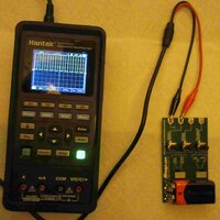
Please Remember... any time your are Diagnosing COPs, EFIs or Solenoids... You MUST Protect your Oscilloscope by using a 20:1 Attenuator installed on the Scope Channel ahead of any Channel Lead (Probe) to mediate HIGH VOLTAGE SPIKES that can Damage your Equipment. Ooops... Almost Forgot... NO PINTLE HUMP IN YOUR EFI WAVE FORM ON SCREEN MEANS IT IS STUCK CLOSED ...AND NOT WORKING!

This is a "KNOWN GOOD" EFI Wave Form:

Injector-Voltage-Waveform.jpg
 
Last edited:

Forum Statistics

Threads
23,316
Posts
637,859
Members
18,518
Latest member
Firebaugh86

Members Online