How To Use PICO #2204A & HANTEK #1008C Oscilloscopes

mrrsm

Original poster
Lifetime VIP Donor
Supporting Donor
Member
Oct 22, 2015
7,733
Tampa Bay Area
Can you Diagnose a Crank-No Start on a 1999 GM or GMC V-8 Truck using a Pin Point Probe Test Light and a DMM? Sure. Maybe ... OR... You could watch what THIS Dude from "The Final Stop Auto Tech" YouTube Channel is up to with what he does with the Oscilloscope Feature of his Autel Diagnostic Tablet to make THIS Ground-2-Ground Diagnosis and Repair with his "O" Scope a SHORT & SWEET One:


Here is the same Dude working on a problem with 'Fresh Engine Swap of a 6L Engine" into a 2006 Trailblazer using THREE Signal Inputs into his "O" Scope to Dope Out a SERIOUS Timing Issue:


And HERE is a Supporting Video from Advanced Level Auto using a SIMILAR Approach to achieve a SIMILAR Diagnostic Result on a SIMILAR Vehicle:


And a "Shade Tree Kid Mechanic" with GOOD Diagnostic Instincts who SORTS IT OUT:

 
Last edited:

mrrsm

Original poster
Lifetime VIP Donor
Supporting Donor
Member
Oct 22, 2015
7,733
Tampa Bay Area
And Now for some Very Inexpensive and Very Cool Oscilloscope Accessories from ROTKEE that are Damned Near MUST HAVES for things like Pressure Pulse Sensing Diagnostics!!!

Guys... THIS is the Kind of STUFF that is normally WAY TOO EXPENSIVE to Find and Buy... So Visit the ROTKEE Link mentioned in this Video if you want to expand upon your "O"Scope Diagnostic Possibilities ...without Going Broke:


NOTE:
In order to make it E-Z-R for anyone interested in purchasing any of the "O "Scope Sensors mentioned in the above Video, I prepared "My ROTKEE Wish List" linked below as a PDF that shows the Images of all these Items by their Names and Prices and (because the Site is Multi-Lingual) by clicking on ANY or ALL of what you might want to buy...they are Hyper-Linked in English back to the Main ROTKEE Home Page.

Also... Drop in at the On-Line ROTKEE Wave Form Library then View & Download a mixture of Known Good and Known Bad Wave Forms... For Knowledge, For Practice and For Comparison against whatever YOUR Troubled Investigatory Wave Forms happen to look like:

GMLL8KNOWNGOODCAMCRANKCORR.jpg

This Place has Great Value to any Automotive Diagnostician using ANY Make or Model of Oscilloscope... Start with observing THESE (92) Chevrolet Wave Forms... Download Them ...and... USE THEM:


Then... REALLY Check Out ALL of The YouTube Videos within this Search String: "Automotive Oscilloscope"... Every Single Chance You GET!


I should have covered this Topic a long time ago, but since. "There Is No Time Like The Present..." Here Goes:

Whenever using the Needle Probes with the 4mm Female Banana Pin Lead attachments, follow the Technique being used by "Diagnose Dan" in THESE Images to avoid damaging the Circuit Wire, The Circuit Wire Insulation OR the Soft, "Gummy" Weatherpack Silicone Seals:

DIAGNOSEDAN1.jpgDIAGNOSEDAN2.jpgDIAGNOSEDAN4.jpgDIAGNOSEDAN5.jpgDIAGNOSEDAN6.jpgDIAGNOSEDAN7.jpgDIAGNOSEDAN8.jpg
 

Attachments

  • ROTKEEWISHLIST.pdf
    44.2 KB · Views: 1
  • DIAGNOSEDAN3.jpg
    DIAGNOSEDAN3.jpg
    83.7 KB · Views: 2
Last edited:

mrrsm

Original poster
Lifetime VIP Donor
Supporting Donor
Member
Oct 22, 2015
7,733
Tampa Bay Area
Can you use an Oscilloscope to "Verify a Bogus Name Brand Spark Plug"...?

Oh Yeah...


mrrsm

Original poster
Lifetime VIP Donor
Supporting Donor
Member
Oct 22, 2015
7,733
Tampa Bay Area
Let's take a moment to *Down-Shift Gears* and take a look at some of the LEAST Expensive Oscilloscopes worth knowing about for The Curious, The Novice and The "O" Scope Newbeez who might want to experiment with one of the Single Channel, Modestly Featured Oscilloscopes that are also Very Reasonably Priced as an Introductory Familiarization Device:

No Offense Intended here...But I DO Need To Warn You... Once you Get Your Feet Wet with making Simple Wave Form Diagnostics:

"THERE'S NO GOING BACK... TO THE RISK OF BECOMING ... A PARTS-CHANGING-HACK"


Disclaimer:

I Do NOT Own or Use any of these Single or Dual Channel Hand-Held Oscilloscopes and I Do NOT Sponsor either the eBay Sellers or the Manufacturers of these Inexpensive Oscilloscopes.

CAVEAT EMPTOR... Buyer Beware:

While purchasing simple "O" scope Systems like these, The New Users should know that while they are NOT designated for use with Automotive Diagnostics... they WILL sense the Wave Forms being investigated during Automotive Diagnoses when they are Set Up Correctly.

Thus it follows on that if New Owners-Users desire to measure High Voltage Modules and Components such as Coil Over Plugs (COP) Coils and EFIs or Solenoids, care must be taken to always install a Hantek 20:1 High Voltage BNC Connector Attenuators in line with any Leads and Probes in order to protect the Oscilloscope from High Voltage DAMAGE. The Hantek 20:1 BNC Connector Attenuators are available on Amazon for around $10.00 to $12.00 + S&H.
 

mrrsm

Original poster
Lifetime VIP Donor
Supporting Donor
Member
Oct 22, 2015
7,733
Tampa Bay Area
I never stop looking for ROTVs (Relevant Oscilloscope Training Videos) but sometimes ...it surprises even ME for what is available to watch on YouTube. The latest stuff concerns dropping in on Joe's Auto Electric YT Channel and ending getting Two Very COOL "O" Scope Sensors that should *Spark* Up some interest if you are just now getting into either Basic Oscilloscope Diagnostics or trying to do some more esoteric Sound and Vibration Diagnostics of seemingly intractable Noisy Suspension Issues.

I'll let HIM describe how they are applied and I'll show you the two that I just got that are SO FRIGGIN' KOOL...and for not too much Moolah, either...(Visit the JAE Store below) :


(1) Magnetic Vibration Sensor (Use in 1-4 Units for "O" Scope Isolation of Suspension Issues)

(2) Rectangular Secondary Ignition Wave Form Sensor (Use with Clear Double Sided Tape)


JOESAUTOELECTRICSENSORS1.jpgJOESAUTOELECTRICSENSORS2.jpg
JOESAUTOELECTRICSENSORS3.jpgJOESAUTOELECTRICSENSORS4.jpg

And here are Three "Diagnostician "O" Scope Karts" being Unveiled BY Three Serious Power Users:


Last edited:

mrrsm

Original poster
Lifetime VIP Donor
Supporting Donor
Member
Oct 22, 2015
7,733
Tampa Bay Area
It is possible to perform Non-Invasive, Sub-System Suspension Noise Diagnostics in the following manner:

Tools:

Windows Laptop Computer using Windows OS
Inexpensive PICO-Scope Two Channel Model # 2204A Oscilloscope
FREE PICO-Scope Automotive Diagnostics Software (Version 6 is preferable)
Download for FREE via www.picoscope.com
Joe's Auto Electric Magnetic Noise Pick-Up Sensors
Joe's Auto Electric Magnetic Lead Supports-Line Holders

Methods:

Attach the Magnetic Pick-Ups to the opposing Wheels or Suspension Sub-Components
Attach and isolate the Sensor Leads via the Magnetic Holders back to the PICO Equipment inside the Cab of the Vehicle all set up and resting upon the Passenger Seat.
Run the PICO-Scope Automotive SW and Set the Voltage to 1-2 Volts DC (Vertical Axis) and Set the Time Base to 10 Second Graticules (Horizontal Axis).

Expected Findings:

In the two following examples, the *Problem Wheel* was instantly identified by the dramatic and obvious increase in the Harmonic Amplitude of the Noise as the Vehicle was first making a Left Turn that showed up as a Gradual Increase in the Amplitude of the Left Wheel Noise (Blue Trace) during the Left Turn. The Red Trace is coming from the Right Wheel with the Sensor placed in the mirror position to the Left Wheel.

Then, the Test Driver made sharp Zig-Zags on the Highway at speed with the results of having the Blue Trace remain instantly Elevated with a slight break in between the two Vertical Trace Lines close together as the Steering shifted sharply from Left to Right. This Wave Form is distinctive as indicating that the Left Wheel was suffering from a Bad Wheel Bearing.

The sequenced images below emphasize the advantages of being able to Isolate the Noise in a Dynamic Driving situation... without ever having to Touch Your Tools:

DONTGUESSTEST2.jpgDONTGUESSTEST3.jpgDONTGUESSTEST4.jpgDONTGUESSTEST4A.jpgDONTGUESSTEST5.jpgDONTGUESSTEST6.jpgDONTGUESSTEST7.jpgDONTGUESSTEST8.jpgDONTGUESSTEST9.jpgDONTGUESSTEST10.jpgDONTGUESSTEST11.jpgDONTGUESSTEST11A.jpgDONTGUESSTEST12.jpgDONTGUESSTEST14.jpgDONTGUESSTEST15.jpgDONTGUESSTEST16.jpgDONTGUESSTEST18.jpgDONTGUESSTEST19.jpg
 

Attachments

  • DONTGUESSTEST17.jpg
    DONTGUESSTEST17.jpg
    43.1 KB · Views: 2
Last edited:

mrrsm

Original poster
Lifetime VIP Donor
Supporting Donor
Member
Oct 22, 2015
7,733
Tampa Bay Area
*Amplifying* (Pun Intended here) upon the information covered in Post #85 & #86... I thought I would array TWO "Joe's Auto Electric" Magnetically Held Vibration Sensors along the Back-Plane of my Ceramic Painted Oven Deck along with a few of his VERY Handy -2 - Have Neodymium Magnetic Oscilloscope Leads Holders that would be necessary to array them on say... under the Steel Frame-Chassis Sections or Stuck to the Brake Assembly Dust Plates on the backs of any of the Four Wheels... or underneath the Suspension, Engine or Transmission Mounts Steel Brackets... or Wherever You NAME IT.

VIBSENSORWITHMAGHOLDERS1.jpgVIBSENSORWITHMAGHOLDERS2.jpgVIBSENSORWITHMAGHOLDERS3.jpgVIBSENSORWITHMAGHOLDERS4.jpgVIBSENSORWITHMAGHOLDERS5.jpgVIBSENSORWITHMAGHOLDERS6.jpgVIBSENSORWITHMAGHOLDERS7.jpgVIBSENSORWITHMAGHOLDERS8.jpgVIBSENSORWITHMAGHOLDERS9.jpgVIBSENSORWITHMAGHOLDERS10.jpgVIBSENSORWITHMAGHOLDERS11.jpg


Getting this Inexpensive Support Hardware and Using these Tactics for deployment of them on or under your vehicle(s) is all very necessary *IF* you intend upon making ANY serious efforts at conducting Automotive Vibration Analysis in ANY of the Three Degrees of Freedom of Motion in The "X"... The "Y" ...or The "Z" Vectors (or any combinations in between) that Automotive Components can create... simply by using YOUR Oscilloscope for such Diagnostics:

3d-axis-colored-on-white-background-vector-17721325-1748973208.jpgdirection-of-x-y-and-z-axis-vector-7810343.jpgPicture4-2-2854812179.jpgproxy-1202936953.png

Beyond post-inspection observations of clearly Broken Components, I don't care HOW sensitive and subtle you MIGHT think that your "Inner Ear gauge & Meter" or your "Seat-Of-The-Pants" Vibration Detection Apparatus might be... I defy ANYONE to explain precisely Which Components (or any combinations thereof) is (are) either causing or contributing to the creation of Mysterious, often Impossible to Locate Vibrations and the Strange Noises they can generate... with any True Degree of Accuracy.

All that said... if you possess either a One, Two, Four or Eight Channel Oscilloscope and THIS Gear... then you can isolate certain suspect components in their Proper X,Y & Z Vectors of Motion... and THEN your Oscilloscope Screen WILL reveal whatever activity is actually taking place.

Now, while I honestly don't believe that it is necessary to take the MIT Mechanical Engineering Course shown in this Linked Video to understand the basics of all this stuff... I suspect that if you have the wherewithal to be reading THIS Topic right now... then you have already Drunk The "O" Scope Kool-Aid by now and are neither afraid to TRY TO DO NEW THINGS, nor afraid of LEARNING HOW TO DO NEW THINGS... and You've already done so ...time and again!.

Nonetheless... Please... Give this Low-Key (BUT Very COOL) MIT Professor half-a-chance at around 34 Minute into his Lecture and you'll be surprised at just how much of what he describes to his students ....is already nested within your Mechanic's Mental Wheelhouse of Understanding:

MIT Mechanical Engineering Course on Vibration:
Covering A Single Degree of Freedom


Vibration Isolation:


Also... Attached below is another "On Topic" White Paper worth digesting that provides even more insights into Vibration Diagnostics and Analysis:

In the end... Even if you 
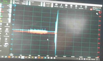
NEVER delve any deeper into this subject than simply placing your Oscilloscope Vibration Sensors 'hither and yon" ... BUT... carefully observe WHERE and observe WHICH VECTOR(S) (X.Y,Z) they wind up being properly situated (pointed) at upon or near to each Suspect Component ....then your Oscilloscope WILL display them as Amplitude vs. Frequency Over Time and THEN you will EASILY figure out the problem from watching "ALL THOSE SQUIGGLES" on your Screen...WHAT Component(s)n are causing the Problems and showing WHEN they started to FAIL (at Certain RPM... During Certain Braking Events... in Certain Gears, Etc.)

THIS Process is a MUCH better approach than merely GUESSING and THEN wind up Buying Suspension Parts, Etc... and LATER finding out that what You THOUGHT were the *Problem Parts* or components turned out NOT to be what was Causing all that RACKET and all those Premature Parts Failures. :>)
 

Attachments

  • 0901d196801082e3_pdf_preview_medium.pdf
    318.8 KB · Views: 1
Last edited:

mrrsm

Original poster
Lifetime VIP Donor
Supporting Donor
Member
Oct 22, 2015
7,733
Tampa Bay Area
I'm always looking for the Ways & Means to invite Folks interested in becoming Good Diagnostic Technicians using Decent Bi-Directional Scan Tools to Join In... and get up close and personal with the "EFFECTS" of problem Engines...and then following on with using the Oscilloscopes and/or Sensitive Digital Graphing Multi-Meters to Dial in on the "CAUSES" versus just reflexively "Throwing Repair Spaghetti Against The Wall ...and just Hoping That Something Will STICK..."

In THIS Video...We get introduced to a Dude who should be YOUR Favorite Kind of Technician... Somebody who "HAS the "GEAR" ...WITHOUT The "Fear"...of FAILURE... that can come along with being intimidated by such seemingly too sophisticated Instrumentation. So HIS approach is to USE THE POWER OF THE ON-SCREEN VISUALIZATIONS ...and just SEE The Problem for What It IS.

The Customer Complaint Work Order Data:

NISSANVERSAMISFIREWORKORDER.jpg

The Average Dude with just a DMM and a "Surface" Lighted Probe will NEVER improve his Diagnostic Skill Set because he will Never be able to SEE enough DETAIL to Know what the Actual Problem Really IS ...but by the same token...The Average Mechanic with even a modicum of patience and interest CAN become a Competent Diagnostician once he KNOWS WHAT HE IS LOOKING FOR.

This Man Demonstrates doing just THAT on a Mid-2000 Nissan Versa sporting a Bad Misfire on Cylinder #3 using the Latest FREE PICO-Scope Version 7 Software (I prefer Version 6) and employing TWO Digital Oscilloscope Input Signals using a Paddle Style Ignition Coil Sensor picking up Secondary Ignition Coil Readings placed over the #3 Coil on a Four Cylinder Engine on Channel 1 with an In-Series 20:1 Voltage BNC Attenuator attached in line to prevent High Voltage (KV) from Damaging his Equipment...AND...while stringing a VERY LONG Channel 2 Lead back to the Tail Pipe to pick up the Engine Exhaust Pulses using a "First Look" Probe inserted therein.

So... Download, Save and Review THIS Video if you are sitting on the fence about getting a Basic, Inexpensive Oscilloscope (Well Documented by Price and Features listed at the Beginning of this Thread)...but have any doubts left about WHY You would want to try this *Stuff* Out.

Stop... Look... and Listen... to his Explanations as he Breaks Down of the Coil Over Plug Wave Form's appearances between What a Known Good Wave Form Looks Like versus What a Bad Wave Form on the #3 Cylinder Looks Like that he can CLEARLY see on his Laptop Screen via the Features of the PICO-Scope Version 7 Software. AND SO...WILL...YOU.

Take note of just how MUCH DETAIL is being captured for later ZOOMED ANALYSIS that tells the story of what has gone wrong ...in EXQUISITE Detail... by a Guy who just wants YOU to SEE WHAT THE PROBLEM IS... JUST BY LOOKING AT THE PICTURES AND COMPARING ADJACENT CYLINDER ACTIVITIES ON SCREEN:


Secondary Ignition Trivia:

 
Last edited:

Forum Statistics

Threads
23,330
Posts
637,981
Members
18,531
Latest member
MEHMET ONUR

Members Online