For quite some time I have wondered about the HDM and Cooling Fan solid state modules operation. So recently I decided to get some readings. What I got was not at all what I expected to see.
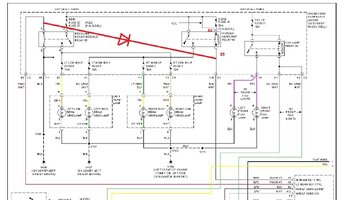
I began with the DRL/Lo beam operation. Here is what I saw reading the control signal from the BCM to terminal #5 of the HDM to chassis ground:
Key Off Engine Off, Lo Beams OFF: battery voltage DC, 0 VAC, 0 Hz, 0%
Key Off Engine Off, Lo Beams ON: ~30mV DC, 0 Volts AC, 0 Hz, 0%
Key On Engine Off, DRL ON: ~2.15 VDC, 3.8 Volts AC, 128.3 hz, 17.8%
Note that to activate the DRL I had to shift out of Park.
Note: when I measured with the engine running the voltages with DRL active were a bit higher but the frequency and duty cycle were the same.
It appears the control signal from the BCM to terminal #5 is always battery voltage whenever the Lo beams are OFF, even when the vehicle has been parked and the network is in sleep mode. I left mine parked and key out for close to 20 minutes and the signal never turned off. I think a loss of this signal would result in the Lo beams turning ON since the power for the Lo beams to the module is hot at all times. Seems like I have read posts where users reported not being able to turn OFF their headlights.
Moved on to the Cooling Fan module and saw similar behaviours as expected since they are the same module.
I'll need to do some testing while driving as testing at idle engine rpms did not always get a response since the fan was already turning faster than the desired rpm would go. But what I saw when increasing the fan speed was the control signal from the PCM would be battery voltage when fan desired speed was less than fan actual speed resulting in a fan clutch OFF condition, a momentary drop to roughly 6 or 7 volts while activating the fan clutch solenoid valve (saw no difference between a 50% command or a 100% command), and the frequency would change from 0 Hz to about 1.99 Hz while the "%" (duty cycle?) went from 0% to about 98.x to99.x%.