GM Class 2 Comm Issue U1000 2004 Escalade

Mark Whitnell

Original poster
Member
Jul 5, 2023
7
Ft Myers FL
ABS and Brake warning comes on, voltage drops to (zero). Ding dong chime continues...No driving difference. Radio goes out. Codes thrown:
P1626 Theft deterrent fuel enable signal not received
U1041 Lost communications with electronic brake control module
U1064 Lost communications with BCM
U1016 Lost communications with ECM Engine control module
U1000 Missing data primary ID
C0455 Front steering position sensor
C0292 ECBM failed to receive data from PCM
U1056
U1062
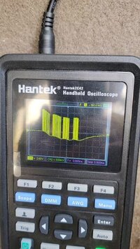
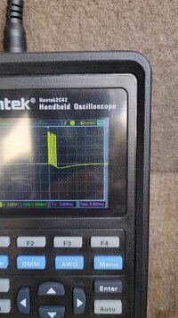
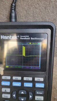
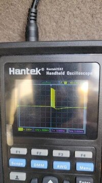
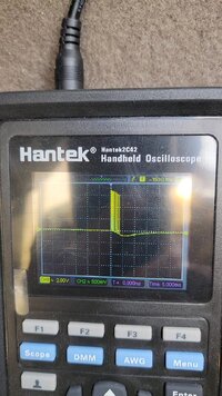
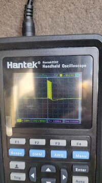
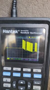
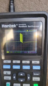
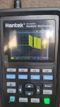
I removed the splice pack 205 comb, scoped each Control Module. Most show data packs report with 7volt high, but the data pack signal falls to below 0, like maybe -1.0v then trails to 0v, before the next packet.
The car starts fine and runs okay. Attached osciloscope scans with BCM + additional pin connected as listed. Some of the scope photos show I believe only the Data from the BCM even tho an additonal pin is connected. I guess no addtional data is sent on that module so you only see the data from the BCM. Note the hig & low voltage. The low dips down below 0v???? Iam guessing the data pack should not go below 0V...any thoughts what I am missing? My scope is set for 2V/div, 5mS
 

Attachments

  • BCM connected + A pin Data to 2nd Splice pack.jpg
    BCM connected + A pin Data to 2nd Splice pack.jpg
    34.4 KB · Views: 4
  • BCM connected.jpg
    BCM connected.jpg
    31.3 KB · Views: 4
  • BCM connected +H pin SCM.jpg
    BCM connected +H pin SCM.jpg
    32.3 KB · Views: 2
  • BCM connected + M pin.jpg
    BCM connected + M pin.jpg
    31.6 KB · Views: 2
  • BCM connected + M pin .jpg
    BCM connected + M pin .jpg
    370.7 KB · Views: 2
  • BCM connected + L pin MSM.jpg
    BCM connected + L pin MSM.jpg
    31.1 KB · Views: 2
  • BCM connected + G pin IPC.jpg
    BCM connected + G pin IPC.jpg
    33.2 KB · Views: 3
  • BCM connected + C pin ABS.jpg
    BCM connected + C pin ABS.jpg
    30.9 KB · Views: 3
  • BCM connected + B pin PCM.jpg
    BCM connected + B pin PCM.jpg
    29.2 KB · Views: 3

TollKeeper

Supporting Donor
Member
Dec 3, 2011
8,081
Brighton, CO
Paging @TJBaker57
Paging @Mooseman
Please pick up the BLUE courtesy phone

I know I am forgetting someone..

What scan tool do you have? I am curious on what modules are being woke up, and responding..
 

Mark Whitnell

Original poster
Member
Jul 5, 2023
7
Ft Myers FL
I dont have a scan tool...I placed order for an Autel MK808S-TS, but it wont arrive til next Tuesday. I dont have a wiring diagram for Class 2 bus, so I used wire colors typical of GM, such as wht-hvac, dk-grn PCM or ECM, LT-grn BCM, pu-data link...all on SP-205.. I posted scans of the devices awake with BCM connected to individual Modules, so you can see which modules are awake from photos....some of the modules dant send data packs, only seeing the BCM data when connected.
 
Last edited:

TJBaker57

Member
Aug 16, 2015
2,907
Colorado
I am going to shoot from the hip here with regards to the less than zero voltages seen on the scope....

I don't think that really matters as long as the receiving circuitry sees the proper highs and lows above and below the specified voltage thresholds. Again, I am just shooting from the hip based largely on things I have read plus my experiences constructing an Arduino project that reads/decodes the SAE J1850 VPW protocols we have here.
 

TJBaker57

Member
Aug 16, 2015
2,907
Colorado
I dont have a scan tool...I placed order for an Autel MK808S-TS, but it wont arrive til next Tuesday
I assume you don't have ANY OBD2 device then? One of these OBD2 Bluetooth (or wifi) adapters along with an Android device and some guidance from yours truly and we can see the actual message frames instrad of just some lines on a scope.


Checking your about info it seems the subject vehicle is a 2004 Escalade with 6.0L??

Does such vehicle operate solely on a Class II serial data bus or does it also run a ISO 15765-4 CANBUS network as well?
 

Mark Whitnell

Original poster
Member
Jul 5, 2023
7
Ft Myers FL
I assume you don't have ANY OBD2 device then? One of these OBD2 Bluetooth (or wifi) adapters along with an Android device and some guidance from yours truly and we can see the actual message frames instrad of just some lines on a scope.


Checking your about info it seems the subject vehicle is a 2004 Escalade with 6.0L??

Does such vehicle operate solely on a Class II serial data bus or does it also run a ISO 15765-4 CANBUS network as well?
It is 2004 escalade 6l. I believe GM came out with this snigle line bus system in the 1990s and used it until the US made it a standard to go with the high/low can buss on 5v. This probably happened is about 2010 or there abouts. Most of the scope signals I have seen dont go below 0v up to 7.5v so that is why I suspect something is drawing down the voltage below 0v....just my thought. I have bought a wifi bluetooth elm327 equal, but it wont be here til maybe friday, and have loaded the torque app on phone.
 
  • Like
Reactions: TJBaker57

TJBaker57

Member
Aug 16, 2015
2,907
Colorado
the US made it a standard to go with the high/low can buss on 5v. This probably happened is about 2010 or there abouts

I believe legislation required CANBUS for the 2008 model years. Even before that for at least the GMT360/370 platform with V8 engines the ECM and TCM were on CANBUS while the rest of the truck was still Class II. The ECM actually used both, the only module to do so.

Any way after struggling with wiring diagrams (automotive schematics SUCK) I found what I was looking for. Looks like no CANBUS for your year. Also, according to the diagrams I have the BCM and PCM have an additional serial data wire between them. Early TrailBlazers etc also have this redundant circuit. This circuit #710 does not go through any splice pack. It likely doesn't matter a whole lot for testing but it is good to know.


elm327 equal, but it wont be here til maybe friday, and have loaded the torque app on phone.


Torque is good for some things but for serious investigations I go for manual control with a standard serial terminal app. I can do far more this way.
 

Mark Whitnell

Original poster
Member
Jul 5, 2023
7
Ft Myers FL
Is this occurence while driving or just at key on?
Dash shows these lights with KeyOn... with KeyOnEngOn chime continues, car drives fine. I will remove splice comb tomorrow and jump 'D' Data Link to 'B' PCM & 'M' BCM, drive car....with all other modules disconnected. Thinking a liitle more, I should check gnd at PCM & BCM. I think they should be tied together somewhere....dont have wiring to tell me tho....maybe I should signup to alldata for a month. Maybe a bad gnd pulling voltage below zero...??? I may have to connect 'G' IPC also so the dash functions.
 

mrrsm

Lifetime VIP Donor
Supporting Donor
Member
Oct 22, 2015
7,773
Tampa Bay Area
Welcome to GMT Nation...

Your "Voltage Over Time" parameters just need a bit of *Tweaking*... Since all Class 2 Serial Packet Data ranges from 0 to 7 Volts DC using Variable Pulse Width Modulation on a Single Wire Network... Try setting your Vertical Voltage Scale to 20 Volts DC and your Time Base to 500 Milli-Seconds and then cop some more Screen Images of the individual Modules in the order they appear in the Splice Pack.... One after the Other.

Take note that if ANY Module is either "Shorted to Positive" ...your initial Voltage Spike on the leading edges of the Packets will climb up to nearly 12 Volts DC. But, if the Network is "Shorted to Ground" then you will enter Negative Numbers on the Voltage Axis.

ANY errant Module can bring the ENTIRE "Ethernet" inside of the Vehicle... DOWN ... so take your measurements at the Splice Pack(s)... NOT at the individual Modules. Once you find out which one is actually causing the problem... then perform your usual "Powers & Grounds" checks next on it ...and go from there if you determine that the BCM turns out NOT being the actual culprit.

Also... Try moving your Vertical Trigger such that you can see the "O" Volts portion of the Scale as close to the very bottom of your Hantek Model #2C42 Hand-Held Oscilloscope Screen as possible. This way... you'll be able to easily see if the Voltage Spike bumps up closer to the 12 Volts DC Level... or not. It is a shame that only the Hantek Model #2D82AUTO features around 80 Automotive Pre-Sets that can make quick work of setting the Machine up for things like this kind of Diagnostic Work.

Taking EVERYTHING off line at the Two Splice Packs and then only adding in One Module at a Time at the Splice Pack(s) while viewing the Oscilloscope ...will help to identify the 'Bad Guy' when the one that does NOT throw a Regular, Tight Square Wave in between 0 to 7 Volts appears on screen.

Some Recommended Videos:

From Will Robinson of Robinson's Auto The BEST Instructions EVER for Class 2 Network Diagnostics:


And for some Fundamentals "Good Stuff" From DeadOnDiagnostics:

 
Last edited:

Mark Whitnell

Original poster
Member
Jul 5, 2023
7
Ft Myers FL
You may find that B and M are always connected by circuit 710 regardless of sp205 comb
Yes these two modules have data line between so they can communicate with each other, but are not connected to the network. They both have to be connected to the SP205 to be on the network. So basically with SP205 comb removed the engine will start and operate sending info on this 710 line between the ECM/PCM & BCM. Thinking a bit more: I will connect my scope to Circuit701 at BCM Connector C3 /Pin B1/yellow and see if the trace looks the same as what I observed connected to DTC Pin2 with both BCM & ECM connected.
 
Last edited:

TJBaker57

Member
Aug 16, 2015
2,907
Colorado
Yes these two modules have data line between so they can communicate with each other, but are not connected to the network.

How interesting indeed! I must admit I assumed it would be the same as the P10 PCM in my GMT360/370 platform.

I will have to check this out for sure! Maybe the Yukon, Tahoe, Escalade operate differently than our GMT360/370 platform?? I will test this when I get a chance.

On my TrailBlazer I simultaneously recorded (separately) all of the message traffic on both the SP205 and related data bus and the circuit 710 for a reasonable time period, enough to make a judgement. The two data recordings were bit for bit identical.

At the P10 PCM there is zero ohms between the two serial data pins, C1:58 & C1:59. So there can be no doubt on the P10 PCM, there is just one data network with a second redundant wire between BCM and PCM.

I have noted that in later yers than my 2002 the redundant line was eliminated.
 

Mark Whitnell

Original poster
Member
Jul 5, 2023
7
Ft Myers FL
Like I mentioned, I will compare the trace on 710 with comb sp2050 removed against the DTC Pin2 with jumper between ECM & BCM on SP205...but wifes Toyota solara conv has leaking Rack & Pinion. Just removed rack waiting on delivery. So maybe tomorrow I will work on Escalade waiting for Rack&Pinion. I would like to know if the voltage going negative approx 1volt is ok or is a ground missing letting the voltage drop below 0volts on the traces I have posted.
 

TJBaker57

Member
Aug 16, 2015
2,907
Colorado
Well it turns out I cannot test my circuit 710. While the wiring diagrams indicate I have that circuit it simply is not present in my 2005 5.3 LM7 Yukon. At least not at the BCM.
 

Mark Whitnell

Original poster
Member
Jul 5, 2023
7
Ft Myers FL
Just got this Autel MK808S-TS. Scanned DTCs, almost all modules had codes. Copied to pdf. Erased codes, rescan, got one code U1000, so a module is bringing down the network. I have seen the Tech 2 show each module status as active, inactive. Can this Autell do the same? If so how do I do that?
 

Forum Statistics

Threads
23,351
Posts
638,246
Members
18,559
Latest member
kraymates

Members Online