ENGINE SWAP: 2004 for 2002 GM ATLAS 4.2L MOTOR

mrrsm

Original poster
Lifetime VIP Donor
Supporting Donor
Member
Oct 22, 2015
7,697
Tampa Bay Area
There is an Old Joke about a Young Man who was running pell-mell down a sidewalk in New York City, freshly shaved and adorned in a Clean Suit with a small White Rose tucked into the Button Hole of his Lapel. Suddenly, an arriving Yellow Cab pulled up slightly ahead of him at curbside and the Elderly German Gentleman Passenger inside stepped briskly out in front of this young fellow. The flushed and excited Kid blurted out,“Oh Please Sir... Can you tell me… How Can I Get To Carnegie Hall?” The Elderly Man smiled wanly and whispered with a cupped hand towards the young man…

Practisss ...Mein Zohn… Practisss...”.

While that scenario bears a lighter and humorous tone ...when applied to continuing the work on the GM 4.2L LL8 Engine Block this evening… the idea behind it is a very serious one. Prior to committing to Bolting up all of the TIME-SERT Hardware and performing this “Surgical Thread-Line Upgrade”… I think it it worth mentioning that before using any such arcane equipment ...it will be very important for anyone intent upon performing this Machine Shop Level Quality of work… is to Practice and Get Familiar With The TIME-SERT Techniques on Something Comparable to the Engine Block Set Up… First:

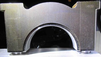
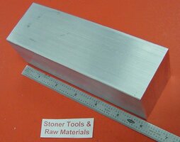
To that end… I've ordered several inexpensive Solid Aluminum Blocks that bear substantial bulk and material large enough to allow me to simply Copy Over the Dimensions of the Mains Bolt Holes from the Aluminum Buttresses inside the Engine Block and then Drill Out and Tap those Holes to include the upper Dowel Cylinder area and the submerged section with the M10X1.50X24.5MM Bolt Hole SERT. Using a Sacrificial Practice Block of Aluminum will make this possible. Then I’ll photo-document all of these Machining Prep Procedures and post them back here before actually performing the Final, Real Job on the (14) Mains Holes in the Upper Engine Block:

2"X 2" 6061 SQUARE ALUMINUM SOLID FLAT BAR 6" long +.25"/-0 T6511 New Mill Stock
ALUMINUMBLOCK2X2X6.jpg


https://www.amazon.com/gp/product/B01F80WLJY?pf_rd_p=c2945051-950f-485c-b4df-15aac5223b10&pf_rd_r=8XHWHKGQYB7ZVJP67FEK

My reasons for making this effort serves three purposes:

(1) I want to Show How These Steps Get Accomplished for those with serious interest in the procedures.

(2) I want to Practice and Hone the Skills I’ve already acquired using THE TIME-SERT SYSTEM:

(3) If any Mistakes Can Be Made... You will want them to happen on the Sacrificial Aluminum Block.

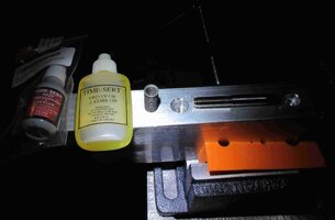
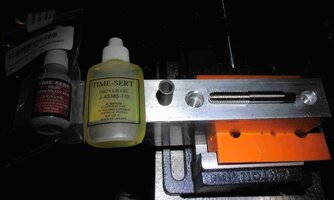
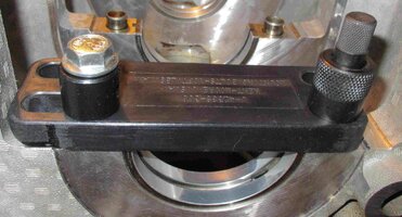
I did a preliminary set up of all these Bits & Baubles... and photo-documented how all of this stuff should look look when properly placed for the purposes of TOOL ALIGNMENTS. These images show that the required TIME-SERT Hardware includes the Modified Base Plate-Alignment Bracket, The Bolt Hold-Down Stand-Off, The Knurled Metric Pin Guide, The Knurled Metric Alignment Pin... and last but not least… The Zinc-Plated 10.9 (Grade 8) M10X1.50X70MM Hold-Down Bracket Bolt. Click on the Link to my latest “Flickr-Bucket” to view/download those images:

https://www.flickr.com/photos/126111508@N07
TIMESERTMAINSETUP.jpg
 
Last edited:
  • Like
Reactions: Redbeard

mrrsm

Original poster
Lifetime VIP Donor
Supporting Donor
Member
Oct 22, 2015
7,697
Tampa Bay Area
NOTE:

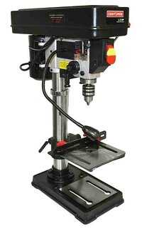
For anyone interested and in need of the Sears Craftsman 10" 1/2 Horse Power Drill Press I will refer to during this particular Post ...Right now... it is On Sale for $159.99 at Sears.com via this Link:

https://www.sears.com/craftsman-10i...SellerId=Sears&prdNo=2&blockNo=2&blockType=G2
SEARSCRAFTSMAN10INCHDRILLPRESS.jpg
The Latin Translation of “Lingua Franca” has different interpretations, depending upon where you find yourself in Human History… But it basically explains the Mixing of Disparate Languages into something Intelligible to persons speaking JUST the other Pure Languages. The concept is kind of like having an unwritten “Rosetta Stone” that allows for the flexible exchange of expressions needed... As in our present purposes when either performing Hands-On Tools or the Mechanical Machining of Metals.

Having acquired all of the components for the creation of a GM LL8 4.2L Mains Cap to Aluminum Engine Block “Practice Test Bed”… there is now a need to translate between the various “Languages of Measurement” in order to achieve as much accuracy as possible when trying to duplicate a mechanical system.

The Metric-SAE Decimal Chart you can see in the attached images serves as the ready means (Lingua Franca) to blend these various languages together and steer us in the right direction. But… For anyone with any tendencies for seeking out the Taps and Drills they may have strewn about in their tool bags or tool chests… Using unfamiliar gear to do this work can invite trouble in the manner of making mistakes before we even start to work on something like this project:


If we intend upon drilling New Holes in Fresh Metal and then Tap them for New Threads… in some cases, it may come as a surprise that getting the Accurate Mating Drill-To-Tap Size might not turn out to be the expected D-BOM (Dead Balls On Measurement) that settles out as Even Numbers. In the case of recreating the Mains Cap Screw Hole Size of M10 X1.50 X 24.5 MM… the preliminary Hole MUST be drilled out smooth to 8.5 MM. The Extruded Aluminum Test Block I chose for this Practice is probably made of a much stronger, Heat Treated T-6061 Alloy than that of the flavor of the Aluminum Alloy GM uses in their “Lost Foam” Sand Castings of the Upper Engine Blocks and Engine Heads and Crankcase components.

So my choice instead of using any particular HSS (High Speed Steel) Drill involved finding a Titanium Nitrided (Ti-N) One-Off 8.5 MM Version to ensure a smoothly drilled Bolt Hole that will allow the Three Fluted 10MM X 1.50 MM Tap to have the “Just The Right Amount Of Meat” left inside for the Tap to slowly chew the New Thread Lines through into the Aluminum Test Block with multiple sprays of “Cutting Oil” induced around the work area. This needs to be done in order to obtain a decent purchase inside of the Drilled Holes and achieve a perfect Thread Line down into the Aluminum Work Piece.

We could all wind up spending Small Fortunes on purchasing various Complete Tap and Drill Sets when trying to obtain only a small fraction of the Set we will require and never again ever have the occasion to use any other portion of that T&D set. However… We CAN save an awful lot of Money by referring to the included Sizing Chart for our Set and then buying only the Tap and Drill sub-components of that set individually necessary to make a Specific Combo required.

After searching on-line at Amazon and other places… It took me quite a bit of looking around before I finally located The One Ti-N 8.5 MM Drill Bit and The One Tapered 10 MM X 1.50 MM Tap I needed for our purposes. As it turned out... a Local Tool Supplier had exactly the right Drill for this Job:


The next decision involves ensuring that the Drill Bit enters the Boring Hole at a 90 Degree Angle to the surface of the Aluminum Block. This is no impediment right now… as I’ll be able to drill out the holes I require using my “Laser-Guided X&Y Bench-Top Sears Craftsman 10” ½ HP Drill Press” to ensure this right-angle relationship happens. However… Later on… when using a Hand Drill on the GM LL8 Engine Block… it will be helpful to have a device that is carefully fastened and arranged to maintain this Right Angle ...and the best item for this purpose is to use a Hardened Steel Drill Guide as seen in this image:


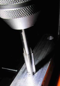
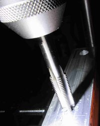
Once the Bolt Holes have been Drilled Out and the Aluminum Test Block is allowed to cool down… the next work portion involves Cutting Threads using the 10 MM Tap and and a Proper “T” Handle Tap Holder. It is important to proceed manually rather than chucking Taps into an Electric Hand Drill… and to work very slowly in order to get a decent “bite” inside of the holes, making slow, deliberate turns downwards on the “T” Handle with only enough pressure to hold the Tool steady at 90 Degrees to the Work Piece. The job will proceed a lot easier if the Tool is Lubricated with Cutting Oil and The Tap itself is allowed to do the Thread Cutting on its own by avoiding the application of any excess amount of downward Hand Pressure.

It follows on that Reversing the Tap every few turns and then cleaning out the Cuttings from the Flutes will remove the extra Aluminum Debris. If not, eventually the Metal Shavings and Junk will pile up and jam in between the Tool Cutting Edges and the Smooth Bolt Holes and could warp or damage the Thread Line as it proceeds all the way through and down to the desired clearance depth. Careful measurements in advance will ensure that the TIME-SERT Installation Tool can pass all the way through the SERT… and have enough room below for expanding and locking the Last Few SERT Threads within that Free Space.

Ergo, knowing how much additional clearance will be required to ensure that Freedom should be added in and allow for the proper ultimate Drill Depth to be correct. So even though the SPACE will be bored clean… it will NOT get used or accessed until the TIME-SERT KIT is employed. Essentially… During this portion of the job… I’ll be trying to Duplicate the Blind Hole Dimensions present in the GM “Stock as A Clock” LL8 Upper Engine Block.

I’m sure that by now… everyone reading along is wondering,“Bobby… Why are you taking so much time and effort with The Drilling and The Tapping of what amounts to be the Stock Crankshaft OEM Bolt Holes with adjacent, Larger Dowel Countersinks as well… if your next move is to simply to Destroy Them All by using the TIME-SERT M10X1.50X24.5 SERT KIT?”

The answer is very simple:

The ONLY way I will know whether or not this TIME-SERT SYSTEM will function better than the Simple, Drilled and Tapped Aluminum Block… is to START with the Test Block under the very same physical conditions that exist inside of the GM LL8 Upper Block.


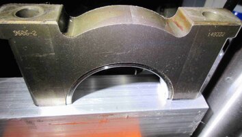
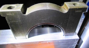
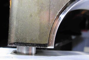
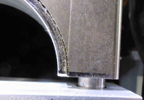
The Last Portion of this work involves Drilling out and Counter-Boring-Counter-Sinking the Hollow Dowel Pin Holes in the Test Block Piece so that Two Dowels I removed from the LL8 Upper Block can be inserted into the Aluminum Test Block and then place the Main Bearing Cap securely on top. After that, the MAIN CAP can be Fastened down according to the GM OEM Installation Instructions, Tightened, Torqued and TTYed in place.

I will want to leave this set-up in stasis for at least One Full Day prior to attempting to Unwind them and see if the TTY Bolts Snap Off. I purchased Two GM OEM Additional Mains Cap Screw Crankshaft Bolts to allow me to perform this part of the Practice and Experiment. After Unscrewing the two Mains Cap Screws-Bolts… I’ll photo-document the Final Results and advise whether or not anything problematic occurred. We will all get to see what happens (Warts and All) and then it can be decided whether or not this TIME-SERT Steel Cylinder Thread Replacement System Works Just As Advertised. Here are the latest images of this work: courtesy my “Flickr-Bucket”:

https://www.flickr.com/photos/126111508@N07/albums/72157704232502675
 
Last edited:
  • Like
Reactions: Redbeard

mrrsm

Original poster
Lifetime VIP Donor
Supporting Donor
Member
Oct 22, 2015
7,697
Tampa Bay Area
The related Video produced by this guy was almost too painful to watch...as he mistakenly used an Extra Long Harmonic Balancer Bolt to DRAW IN the Harmonic Balancer on this GM V8 after he swapped in a lot of Performance Upgrades. And then JUUuuuuuuust B4 the HB was moved all the way on the OD of the Crank... The Impact Gun he was using tightened that LS Bolt so damned hard ...that suddenly...it started spinning without resistance. After that he "wound" up dragging out ALL of the Internal Crankshaft Threads ,..Right along with his "Brilliant" Extra Long LS Crank Bolt.

"OUCH... OMFG! ....WTF am I Going to do NOW?" This is an Object Lesson for ANY Mechanic to NEVER use an Impact Drill to Draw In a TTY Crankshaft Bolt on a Press Fit Harmonic Balancer Installation. The Proper Tool(s) for these jobs ARE very expensive... but as it gets proven in this example... VERY INDISPENSABLE.

From around 14 Minutes into this video... Let The Games Begin...


Enter TIME-SERT to the Rescue... And so while I continue to prepare to perform what the VOP (Video Original Poster) works on with a Cast Nodular Iron Crankshaft Repair...Times (14) inside of the GM 4.2l "Lost Foam" Cast Aluminum Engine Block... if you watch how he salvages this otherwise Totally FUBARed V8 Project... it will give you a much better idea of why I want to install TIME-SERTs into the (14) Crankshaft-Mains Bolt Holes of my LL8 Engine Block.

Mind you... while I'm not crazy about the sloppiness of his Technique when using this TIME-SERT Kit before installing the Crankshaft, Main Caps and the Cradle... the End Results shown in this Video will speak loudly for choosing TIME-SERTs over Common Steel Wire Helicoils. More to Follow on MY Project shortly... as soon as some small tools I need for my 10" 1/2 HP Drill Press arrive ... sometime around Jan-2-4, 2019:

 
Last edited:
  • Like
Reactions: Redbeard

Redbeard

Member
Jan 26, 2013
3,476
And it isn't his first time with this mistake "oh I've had this happen before" removing the threads from the crank! And he still didn't learn after the first time.
 
  • Like
Reactions: mrrsm

mrrsm

Original poster
Lifetime VIP Donor
Supporting Donor
Member
Oct 22, 2015
7,697
Tampa Bay Area
When using either a Hand-Held Drill or Drill Press... most of us would just try and “Eye-Ball” everything for making alignments during this kind of procedure… but for the sake of a few Bucks... and a few extra minutes of preparation using this kit… the resulting improvement in the Drill Alignment Accuracy can make a very big difference in the outcome of such projects. Of course… the “GM 4.2L LL8 Mains-Bolt Hole TIME-SERT Test Bed” procedures under scrutiny right now really demands this level of precision.

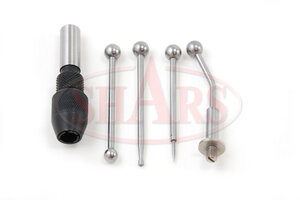
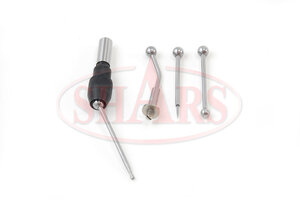
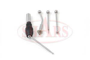
It follows on that If you regularly rely upon the use of a Stable Drill Press and demand as much accuracy as possible (...short of using an Industrial Grade Bridgeport Milling Machine or its ilk...) ...for right at $12.50 with S&H included over on eBay… You can obtain a small “SHARS Wiggler” Tool Kit that has a proper assortment of (5) sub-tools, including the Colette, used to either find the Dead Center of a Drill Point in your Marked Work Metal Material… or determine the Center of a Hole and/or establish the position(s) of the work in all three axis positions before Drilling or Milling into the Work Piece.

What is MOST interesting about using the Needle Sharp Pointer 'Wiggler' is the fact that if your Quill or Drill Chuck (or BOTH) have any looseness or mis-alignment in their Axis of Rotation, the Pointer WILL compensate for these discrepancies and eliminate those problems completely. This action then allows the Newly Chucked Drill Bits, regardless of their sizes, to find their actual On-Target, Point of Spin each and every time. One last assist here is that by using a Better Quality Milling Vise sporting very fine X&Y Milling Machine-Like adjustment features to mount the work for these jobs, you'll improve the ease of achieving faster and better Drilling Alignments:

https://www.ebay.com/itm/SHARS-4-WI...e:g:9LQAAOSwwbdWKjxi:rk:1:pf:1&frcectupt=true

SHARS1.jpegSHARS2.jpgSHARS3.jpg

The link below to my “Flickr-Bucket” shows the images of the SHARS Brand of this Kit… which strikes a nice balance between Price and Tool Quality, making it something worth having in your Tool Inventory. Don’t be overly impressed by the Mitutoyo “Name Brand” flavor of this kit as offered on Amazon for around $21.00 ...as many of the post-purchase impressions indicate that kit as being a disappointment in quality and performance. This simple Graphical Video describes how to use this inexpensive ‘Wiggler Tool Set’:


...our Old Machinist Friend, "Tubal" (mrpete222) humorously demonstrates hands on, "How to Use the Wiggler Tool Set" and "How to Make the Pointer Version of this Kit" on his Metal Lathe and Milling Equipment:


https://www.flickr.com/photos/126111508@N07/albums/72157675220328698
 
Last edited:

mrrsm

Original poster
Lifetime VIP Donor
Supporting Donor
Member
Oct 22, 2015
7,697
Tampa Bay Area
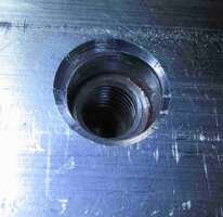
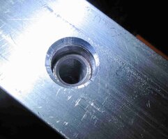
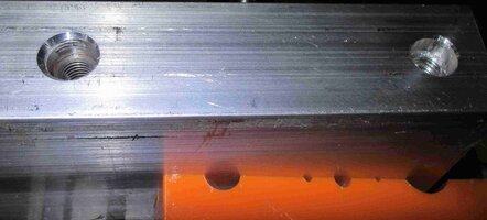
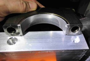
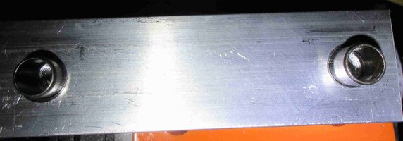
It won’t seem like it for most of the people following along with this “Endless Thread”… but the work I finished this evening is a very meaningful Landmark to me. As you can see from the Link to my “Flickr-Bucket”… I finally managed to accomplish the following Machining work on the Aluminum Test Block as follows that WILL eventually allow me to TEST THE TIME-SERT:

https://www.flickr.com/photos/126111508@N07/albums/72157704232502675

(1) Bored the Blind Hole for the Stock OEM 10MM X 1.50MM X 54MM to a smooth OD of 8.5MM.
(2) Bored the surrounding Hollow Dowel Pin Hole to an ID of 13MM and down to an 8MM Depth.
(3) Chamfered the Dowel Pin Hole OD to a 45 Degree Angle.
(4) Tapped the Center-line 8.5MM X 54MM Hole with a 10MM X 1.50MM X 50MM Tapered Tap.
(5) Test Fitted the GM OEM Crankshaft Mains Dowel Pin ....a GREAT Fit!
(6) Test Threaded In (2) GM OEM Mains Cap-screws (Bolts) to Final Depth.
(7) Test Fitted the GM OEM Chamfered Mains Dowel Pin AND Threaded in a Stock Mains Bolt.
(8) This Completes (1) of the (2) Blind Hole Set-Ups… The NEXT one will be for the TIME-SERT.

While I believe that I achieved making a Nice, Clean Threaded Blind Hole… I still want to obtain a 10MM X 1.50MM Bottoming Tap… and take the Completed Thread-Line as Deep as it will go into the Aluminum Test Block. I’m ordering the Tap early this morning… Amazon’s fulfillment is Excellent ...so it should not take long to get here. In the mean time… I’ll be working on making the Second Blind Hole using the #7 Main Cap as my “Compass”.

I’m guessing that some of our Professional Machinists are probably chuckling by now at what “Child’s Play” this work must look like to them. But in the absence of having a Professional Machine Shop Metal Lathe, a CAD Machine ...or a Milling Machine to perform this work… I have to make the most of what I understand of Metal-Working and use what Tools I can gather to try and create what amounts to literally being a GM LL8 4.2L Upper Block Crankshaft Mains Bolt Holes Mock-Up as accurately as I can. Here are the latest images… and I must say that even if I’ve made a “Dog’s Dinner” out of this so far… seeing how well everything fits together...”Just...So...OEM”… is VERY satisfying. :>)

What I have in mind to do next is to make a Direct Performance Comparison between the Two Bolts holding down a Single Main Cap. And so, I'll keep the presently finished First Bolt Hole in its OEM Condition... and perform these Identical Procedures on the Opposite Main Cap Bolt Hole and THEN finish that task by following all of the TIME-SERT Insert installation procedures. After that, I'll mount the Aluminum Test Block into the Cast Iron Vise, Align the Steel Main Cap... Thread in Both opposing OEM Main Cap-Screws (Bolts) after APPLYING A VERY LIGHT COATING OF TIME-SERT INSERTION TOOL OIL the same for each Fastener.

Then, following @m.mcmillen 's suggested procedures for gradually tightening down both Fasteners in Stages until the First Torque is achieved... I'll perform the Last Detail of applying the Final Torque To Yield (TTY) Degree of Angle to BOTH Cap-Screws (Bolts) and finish the task. I'll allow the Aluminum Test Block to Rest for 24 Hours before moving on with the next observations.

Afterwards, I'll unwind the Two OEM Cap-Screws (Bolts) and examine their Threads, Shanks and also check the Threaded Holes in the opposing sides for any signs of Metal Fatigue, Stripped Aluminum Threads or Stretch-Crack Failures on any kind. I will also be making some additional comparisons regarding any differences in their Measured Bolt Lengths both Before...and then After they are Unfastened.

I'm curious to determine whether or not the Mains Cap-Screw (Bolt) Fastened into the TIME-SERT Bolt Hole stretches MORE or LESS as a result of the Steel on Steel mating surfaces vs. the OEM Steel to Cast Aluminum present in the GM Stock Engine Assembly. Time will tell...

Everything will be memorialized in Photos of course...and IF the News turns out to be GOOD... Then I'll proceed with performing the installation of the (14) TIME-SERT Crankshaft Mains Bolt Holes Upgrade as planned. If NOT... then I WILL abort using this procedure entirely and advise everyone as to the reasons why I have to take this action. More to Follow...

https://www.flickr.com/photos/126111508@N07/albums/72157704232502675
 
Last edited:

mrrsm

Original poster
Lifetime VIP Donor
Supporting Donor
Member
Oct 22, 2015
7,697
Tampa Bay Area
After all this self imposed "Sturm Undt Drang"... its a pure pleasure to complete the Machining Preparation Phase. Tomorrow, I'll Bolt Down the Main Cap on Top of the Aluminum Test Block. One Bolt will occupy the "Stock as a Clock" OEM Thread-lines Drilled and Tapped into Bare Aluminum... while the other one will "wind" up in the opposing side with a TIME-SERT Threaded Carbon Steel Cylinder bearing the identical Metric Size and Thread Pitch of 10MM X 1.50MM X 24.5MM. Then it will just be a matter waiting 24 Hours before loosening the Two Bolts.

If you want do this type of repair... prepare by RTFM from TIME-SERT First. Anybody with a Reasonable Mechanical Acumen and possessed of Common Sense and Good Judgment ...should be able to Use the TIME-SERT Kits of All Stripes to Very Great Effect and for any number of Permanent Metric Thread Repairs for Damaged or Unsuitably Threaded Bolt Holes that DESERVE TO BE IMPROVED ...WHENEVER POSSIBLE.

Please take a moment to look over how the Final Machining leads to achieving the desired results of Upper Engine Block Emulation with complete success. After a Good Night's Sleep... I'll add more images and include the list of actions needed for the objective Main Cap Bolt Down Procedures and later... finish with the accurate observations and results of all this work:

https://www.flickr.com/photos/126111508@N07/albums/72157704232502675/with/31937679157/
 

mrrsm

Original poster
Lifetime VIP Donor
Supporting Donor
Member
Oct 22, 2015
7,697
Tampa Bay Area
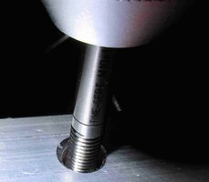
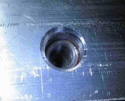
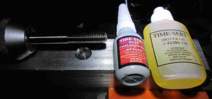
This is a partial Pictorial representation of the Final TIME-SERT Installation Procedures necessary in this case for making a Finished Aluminum Test Block. However, the steps they follow are Identical to ANY such Thread Repair Jobs, regardless of the Hole-Depth Dimensions, Metric Sizes of the Fasteners or Differences in the various TIME-SERT Kits required. Some of these images are a bit out of sequence, as I needed to stage the views AFTER each portion was completed in order to complete the job steps in order and without any interruptions:

TIMESERTTESTFINAL1.jpgTIMESERTTESTFINAL2.jpgTIMESERTTESTFINAL3.jpgTIMESERTTESTFINAL4.jpgTIMESERTTESTFINAL5.jpgTIMESERTTESTFINAL6.jpgTIMESERTTESTFINAL7.jpgTIMESERTTESTFINAL8.jpgTIMESERTTESTFINAL9.jpgTIMESERTTESTFINAL10.jpgTIMESERTTESTFINAL11.jpgTIMESERTTESTFINAL14.jpgTIMESERTTESTFINAL15.jpgTIMESERTTESTFINAL16.jpgTIMESERTTESTFINAL17.jpgTIMESERTTESTFINAL18.jpgTIMESERTTESTFINAL19.jpgTIMESERTTESTFINAL20.jpgTIMESERTTESTFINAL21.jpgTIMESERTTESTFINAL23.jpg
 
Last edited:

mrrsm

Original poster
Lifetime VIP Donor
Supporting Donor
Member
Oct 22, 2015
7,697
Tampa Bay Area
With the focus here being from Post #132 though to around Post #150 about the GM 4.2L LL8 Cylinder Prep, Pistons and Rings... I just spotted what I consider to be THE BEST Ever Instructional Video on, "How To Properly Use a Ball Hone", with the possible exceptions that if "I" were this person... "I" would literally have used up ROLLS of Blue Painter's Tape prior to this work in order to seal up all the open unrelated Block Interior Spaces to prevent the distribution of ANY Ball Hone Abrasive Cast Off and Oily Cylinder Metal Residue from Decorating ALL OF THE HIDDEN SPACES INSIDE THE NAKED ENGINE BLOCK.

The other thing would be to NOT use WD-40 as a Honing Lubricant, but choose instead to use a Proper Hone Oil! With all of those proper criticisms set aside, besides being So Very Easy On The Eyes... Britney DOES Demonstrate THE VERY BEST CYLINDER HONING TECHNIQUE (Stroke vs. Drill Rotation Speed) imaginable while using a Ball Hone fitted to a Battery Powered Hand Drill.

(1) Start the Drill Turning BEFORE the Hone Enters The Cylinder.
(2) Establish a Consistent Inward- Outward Motion from Top to Bottom.
(3) Avoid Over-Speeding the Drill...Use a "One-One Thousand" Cadence.
(4) 15-20 In-Out Strokes should do The Trick for a 45 Degree "Hash" Angle.
(5) Clean Out the Cylinders with Warm, Soapy Water and DRY THEM ASAP.
(6) Oil Each Cylinder with a Water Displacing Lubricant.
(7) Seal The Block On The Stand with a Large Heavy Mil Plastic Bag and Tape Shut.
(8) Unseal ONLY on the Build Days and Re-Seal when NOT Fully Assembled.
(9) Use a Brand New Ball Hone for Each Engine Re-Build!
(10) Keep Replacement Drill Batteries Handy & Change them Often.

The idea here is to achieve the proper, consistent "Hash Lines" necessary for a GOOD Piston Rings to Cylinder Wall Seal during the Initial Break-In Period by ensuring a 45 Degree Angle whenever using a 400 Grit Ball Hone. This is ESPECIALLY Important if your Compression Rings are Moly Impregnated!! Anyhow... Download, Save, Review and Review THIS Video often for Practice Purposes and of course, by all means... Enjoy Learning New Things from Britney. Somehow... I just KNOW that you're going to! :>)


For More Technical Engine Post Hone Clean Up and Assembly Information:


PS... OMG... Look at that "Halloween Pumpkin Orange and Midnight Black" Paint Motif on her Car! One other observation... Notice how Britney INVERTED the Engine Block BEFORE she took off on her Sidewalk Jogging Jaunt with that Stand Mounted Engine? Doing so LOWERED The Center of Gravity... making it MUCH less likely that she might accidentally TIP Engine the Stand Over. :>)
 
Last edited:

Forum Statistics

Threads
23,313
Posts
637,830
Members
18,518
Latest member
bobby2175

Members Online