- Jun 22, 2014
- 1,576
One morning when I started my TB the engine cooling fan made a noise like a jet fighter when I drove off, right away I thought well I need a new fan clutch then. Being to confident I thought these trucks had a fan clutch like all the other cars and trucks so I just order a new one without doing any diagnostic on what the problem really was.
Cost me a nice chunk of $ just to find out that I still had a jet engine under my hood after installing my new fan clutch, so back to basic and do a proper diagnostic before replacing expensive parts.
First check what DTC is stored in the PCM, there are different diagnostic procedure depending on what code was triggered, the fan clutch have multiply DTC that can be triggered. This write up is for DTC P1481 only and no other trouble code.
DTC = Diagnostic Trouble Code
PCM = Power Control Module could also be called ECM (Engine Control Module)
DMM = Digital Multi Meter
Second thing is to print out diagnostic procedure from the shop manual, you can find it and DL here:
http://gmtnation.com/forums/topic/361-need-service-manuals-get-them-here/
Go to Engine Cooling and print out page 2,4,5 and pages 30 to 35 the diagnostic for P1481 starts on the bottom of page 30.
Here's my setup for diagnostic, you don't need a Tech2 to do this but it's a little easier. The only thing you need the Tech2 for is to see if the PCM can read the rpm on the fan when engine is running and the clear the codes. In my case the PCM couldn't read the rpm on the fan (0 rpm in the Tech2)

Here's my printed documentation, you need this and read it carefully and do not skip or jump any parts of the diagnostic.

So I follow the test by the book, well I could skip or jump the part were they test to see if the fan clutch is working or not because I just installed a brand new fan clutch so I knew it was nothing wrong with that one.
When you want to probe a connector do it from behind of the connector, do not poke a sharp object through the insulation of the wires, when you do that you get moister and salt water corrosion creping inside the cable and eventually the wire brakes inside the insulation in a place you have no idea where.
First I tested the power and ground to the fan clutch, no problem and I could eliminate any problem with the fan clutch relay, fuse or ground.
After that I went by the book and finally found out that I had no 5 volt reference signal from the PCM to the fan clutch, now the question was did I have an open circuit on the 5 volt reference signal or a bad PCM.
You don't have to have the connector on the fan shroud connected to the fan clutch connector when you do the testing for reference signals etc.
IMPORTANT! I suggest you use a thin paperclip when you probe the connector both in the front and rear. You don't want to expand the pins in the connector to much and they will not give a good connection when you reconnect it to the fan clutch connector.
Important DISCONNECT BATTERY before you proceed if you don't have a lot of experience with diagnostic procedure on Power Control Modules and Class2 bus signals, very easy to fry things.
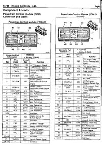
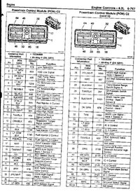
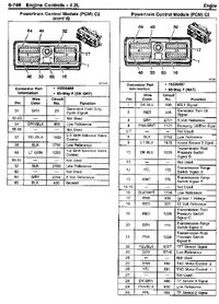
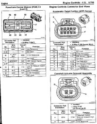
You need to remove the natural (white) and the dark gray connector from the PCM and check on the printouts the pin location you want to check.
E.i the 5 volt reference signal is connector C3 (natural) and pin 60 on the PCM, on the fan clutch connector it's the gray wire in location E.
Connect your DMM set to resistance (Ohm) between the pin 60 and pin E to measure the resistance in the cable, on my picture you can see I had no resistance at all (OL) = broken wire between the PCM and fan clutch connector.

When I had all the connectors apart I also checked so non of the 3 wires connected between the PCM and fan clutch connector was grounded inside the wire loom by a short or something else.
I also triple checked everything before starting to cut any wires, make sure the pins in the connectors match the color of the wire and use the DMM on resistance if you are not sure to measure that each pin is connected with the other one.
Time to run a new wire from the PCM to the fan clutch connector because trying to find where it's broke in the wire loom takes way to much time and effort. Easier to run a new wire, IMPORTANT try to keep the area of the new wire the same area as stock one so you wont get to much or to little resistance in the new wire that will mess up the PCM readings from the fan clutch.
Picture of my new wire solder with the old one, do not leave the broken wire connected to the new one incase the old wire is shorted to ground some where inside the wire loom. And always solder with heat shrinking tube so you get a moister free connection.

I always run my wires in a loom to protect them from wear and tear, specially in a engine bay. Also give the wire some slack between the engine and body so the wire wont stretch to much from when the engine is moving around when you do a WOT race.
Finished it's looking like this, just to bad I spent almost $500 on a new fan clutch when all I needed was about 2-3 hr diagnostic and a couple of feet new wire.
On the fan clutch connector you open the OEM wire loom and then cut the cable you want to replace, same here do NOT let the old broken wire be connected to the new one.

Attaches is printout on PCM connectors that I stole from our old site. Feel free to ask questions if you have any.
Cost me a nice chunk of $ just to find out that I still had a jet engine under my hood after installing my new fan clutch, so back to basic and do a proper diagnostic before replacing expensive parts.
First check what DTC is stored in the PCM, there are different diagnostic procedure depending on what code was triggered, the fan clutch have multiply DTC that can be triggered. This write up is for DTC P1481 only and no other trouble code.
DTC = Diagnostic Trouble Code
PCM = Power Control Module could also be called ECM (Engine Control Module)
DMM = Digital Multi Meter
Second thing is to print out diagnostic procedure from the shop manual, you can find it and DL here:
http://gmtnation.com/forums/topic/361-need-service-manuals-get-them-here/
Go to Engine Cooling and print out page 2,4,5 and pages 30 to 35 the diagnostic for P1481 starts on the bottom of page 30.
Here's my setup for diagnostic, you don't need a Tech2 to do this but it's a little easier. The only thing you need the Tech2 for is to see if the PCM can read the rpm on the fan when engine is running and the clear the codes. In my case the PCM couldn't read the rpm on the fan (0 rpm in the Tech2)
Here's my printed documentation, you need this and read it carefully and do not skip or jump any parts of the diagnostic.
So I follow the test by the book, well I could skip or jump the part were they test to see if the fan clutch is working or not because I just installed a brand new fan clutch so I knew it was nothing wrong with that one.
When you want to probe a connector do it from behind of the connector, do not poke a sharp object through the insulation of the wires, when you do that you get moister and salt water corrosion creping inside the cable and eventually the wire brakes inside the insulation in a place you have no idea where.
First I tested the power and ground to the fan clutch, no problem and I could eliminate any problem with the fan clutch relay, fuse or ground.
After that I went by the book and finally found out that I had no 5 volt reference signal from the PCM to the fan clutch, now the question was did I have an open circuit on the 5 volt reference signal or a bad PCM.
You don't have to have the connector on the fan shroud connected to the fan clutch connector when you do the testing for reference signals etc.
IMPORTANT! I suggest you use a thin paperclip when you probe the connector both in the front and rear. You don't want to expand the pins in the connector to much and they will not give a good connection when you reconnect it to the fan clutch connector.
Important DISCONNECT BATTERY before you proceed if you don't have a lot of experience with diagnostic procedure on Power Control Modules and Class2 bus signals, very easy to fry things.
You need to remove the natural (white) and the dark gray connector from the PCM and check on the printouts the pin location you want to check.
E.i the 5 volt reference signal is connector C3 (natural) and pin 60 on the PCM, on the fan clutch connector it's the gray wire in location E.
Connect your DMM set to resistance (Ohm) between the pin 60 and pin E to measure the resistance in the cable, on my picture you can see I had no resistance at all (OL) = broken wire between the PCM and fan clutch connector.
When I had all the connectors apart I also checked so non of the 3 wires connected between the PCM and fan clutch connector was grounded inside the wire loom by a short or something else.
I also triple checked everything before starting to cut any wires, make sure the pins in the connectors match the color of the wire and use the DMM on resistance if you are not sure to measure that each pin is connected with the other one.
Time to run a new wire from the PCM to the fan clutch connector because trying to find where it's broke in the wire loom takes way to much time and effort. Easier to run a new wire, IMPORTANT try to keep the area of the new wire the same area as stock one so you wont get to much or to little resistance in the new wire that will mess up the PCM readings from the fan clutch.
Picture of my new wire solder with the old one, do not leave the broken wire connected to the new one incase the old wire is shorted to ground some where inside the wire loom. And always solder with heat shrinking tube so you get a moister free connection.
I always run my wires in a loom to protect them from wear and tear, specially in a engine bay. Also give the wire some slack between the engine and body so the wire wont stretch to much from when the engine is moving around when you do a WOT race.
Finished it's looking like this, just to bad I spent almost $500 on a new fan clutch when all I needed was about 2-3 hr diagnostic and a couple of feet new wire.
On the fan clutch connector you open the OEM wire loom and then cut the cable you want to replace, same here do NOT let the old broken wire be connected to the new one.
Attaches is printout on PCM connectors that I stole from our old site. Feel free to ask questions if you have any.
Attachments
Last edited:
