So far on this rig I'd replace the fuel pump and then I had to replace the starter because the starter went out and then I replace the PCM because I was told it was bad now I have another crank no start , no fuel to the rail, no power going to the fuelpump @ the fuse relay I'm getting 12v's on pin 30 , solid ground on pin 85,good current current going back on pin 87 when a jumper wire is placed in pin 87from 30. However only .27v's on pin86 with or without the key turned? Help please thanks in advanced
You are using an out of date browser. It may not display this or other websites correctly.
You should upgrade or use an alternative browser.
You should upgrade or use an alternative browser.
2006 Gmc envoy Denali xl
- Thread starter MadMike
- Start date
Welcome to GMT Nation...
To help you find the correct Diagnostic Approach... You can get a FREE Complete GM OEM Digital Service Manual for your Specific Vehicle ...Courtesy @Mooseman at this First Link:
 gmtnation.com
Have look at this Thread and pay special attention to the Posts that cover Problems with the Ignition Switch:
gmtnation.com
To help you find the correct Diagnostic Approach... You can get a FREE Complete GM OEM Digital Service Manual for your Specific Vehicle ...Courtesy @Mooseman at this First Link:
Need service manuals? Get them here!
********* Please note that the FireFox browser has issues with the password handling and that these downloads are not under HTTPS, flagging them as security risks. Chrome and Edge work fine once you allow the download. ********* ATSG 4L60E Manual 4L60E Rebuild Manual 2005 GMC Envoy XUV...
Have look at this Thread and pay special attention to the Posts that cover Problems with the Ignition Switch:
06 Trailblazer SS no crank/no start diagnostics
Just joined this forum and I'm also on a few SS forums. Bought this truck new and have been plagued with this problem and always have gone the ignition switch route replacing at least 6! Two under warranty 4 doing it myself. Gets it going and starts regularly for up to a year maybe and then the...
Last edited:
so if you do the jumper pin from 30 to 87, your fuel pump runs, correct?
IF so, it would appear that you aren't getting the "pull up voltage" on 86 which should come from the PCM. As mentioned, it could be an ignition issue causing the PCM to not have the right conditions to allow for fuel activation.
you indicate a new pcm was installed... has the truck been started since?
one test for the PCM is to turn the key to ON (not start) and then the check engine light should light and STAY on "forever" (ie. as long as the key is in ON)... if this does not happen then you have an "unhappy PCM".
Last edited:
During the installation of the PCM that was already programmed by the vin to the Envoy the three steps of leaving the key on for 10 minutes each until the security light went off was done and I could not get a start from the motor until the third time once that was complete all security lights and other lights that was on the dash went off however I do have a check engine light on but it was on prior due to a O2 sensor that needs to be replaced that I just haven't got around to doing yet because the car was running just fine even though i had a bad O2 sensor. So far this afternoon I cleaned all the ground connections send them down put them back together with Dielectric grease still getting same result on the fuse block what ahead and took the fuse block off of the car going to see if I have a burnt copper wire inside the fuse box ignition switch has already been replaced but I did notice something funny maybe you can help shut the car off battery disconnected and then hook the battery backup put a pin inside of the fuse panel on the PCM pull of the fuse I get it battery voltage for approximately 2 seconds then it drops like a rock to .27volts.
Mooseman
Moderator

do not confuse the "check engine" status during normal running and the test that I suggested... they are TWO different statuses. From your description, it is NOT clear that you did the test as suggested.During the installation of the PCM that was already programmed by the vin to the Envoy the three steps of leaving the key on for 10 minutes each until the security light went off was done and I could not get a start from the motor until the third time once that was complete all security lights and other lights that was on the dash went off however I do have a check engine light on but it was on prior due to a O2 sensor that needs to be replaced that I just haven't got around to doing yet because the car was running just fine even though i had a bad O2 sensor. So far this afternoon I cleaned all the ground connections send them down put them back together with Dielectric grease still getting same result on the fuse block what ahead and took the fuse block off of the car going to see if I have a burnt copper wire inside the fuse box ignition switch has already been replaced but I did notice something funny maybe you can help shut the car off battery disconnected and then hook the battery backup put a pin inside of the fuse panel on the PCM pull of the fuse I get it battery voltage for approximately 2 seconds then it drops like a rock to .27volts.
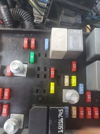
Sorry for any confusion and budwich I appreciate your help👍🏼 so yes I have turned on the key and left it on for an hr check engine light still on , on pic bottom right has battery voltage on all the time bottom left has ground all the time ,top left I have a direct line from fuse panel to fuel pump, top right I have power now after I tore apart the fuse panel blow it out with an air compressor spray done with WD specialized silicone and then reassembled however I have a blown fuse LOL to let you know in an hour it's a half hr drive 1 way to the parts store😥🤦♂️
Keep in mind top-right was only getting .27 volts prior now I'm getting battery voltage on that top right. Prior to me disassembling the fuse panel
Keep in mind top-right was only getting .27 volts prior now I'm getting battery voltage on that top right. Prior to me disassembling the fuse panel
Attachments
Okay that didn't work at all it seems it when the fuse has a load on it the PCM power top left pin stops producing power the moment the load is reduced the PCM produces power again?
:-( I am having a hard time following what you are describing / writing. I understand about the "key on" state... so you have a good pcm state.
You confirmed something about a "direct line from the fuse panel to the fuel pump"... but you didn't confirm that you can then cause the fuel pump to run.
You indicate that you had a blown fuse... but what is the fuse. You need to indicate fuse numbers along with "label/description" to help make things clear.
I don't understand what you mentioned here... "Okay that didn't work at all it seems it when the fuse has a load on it the PCM power top left pin stops producing power the moment the load is reduced the PCM produces power again?"
with your picture, you can add text labels and arrows to help highlight things.... that would be good.
okay so below I attached a picture again same picture but with a Color code, red is hot all the time white is ground because black doesn't show up well in the picture yellow is the computer PCM and gray is the fuel pump when I attach slot red with slot Gray fuel pump kicks on and keeps on running because there's no control when I attach yellow to Gray it pulls a prime on the fuel pump and then kicks off this is with the key on so the blown fuse was actually a blown relay ,relay 41 but it wasn't blown that's why I stated it did not work, at this point I've been working on this rig for a month I've came up empty-handed everything I've thrown at it I waited three weeks for a computer - PCM that's why I reached out to you guys set back to the subject on the color coordinated diagram I posted below if I put leads wire leads going into the holes up to my relay it kicks on for a split second and then kicks off when I try to start the car it does not kick back on however when I attached the fuse The yellow section that is highlighted loses power I have attached an ohmmeter to The yellow section and the minute I attached the relay 11.47 volts goes to zero sorry for any confusion I'm just trying to help you help me LOL
Attachments

well... now I think we have some "communication progress"...  going from a fuse to a relay is quite a jump along with a number so that this can be traced in reference material.
So based on your recent description, you know that your fuel pump works from the fuse box out... which is what I think you were saying from the start... just my lack of interpretation of the earlier text.... sorry.
I am still having trouble with
"when I attach yellow to Gray it pulls a prime on the fuel pump and then kicks off this is with the key on so the blown fuse was actually a blown relay ,relay 41 but it wasn't blown that's why I stated it did not work" ??? you jump the contact marked yellow to the contact marked gray and the pump runs.... this is without the relay in place / connected and none of the other contacts (red and white) connected, right?
Going back to your previously descriptions, can you please indicate your pin number to color to voltage reading (no relay in place), with key off, and again with key on.... again, just ensure we are "seeing" the same thing that you are "seeing" cause our "internet eyes" may not be connected just yet...
One other thing... what engine is in your vehicle?
going from a fuse to a relay is quite a jump along with a number so that this can be traced in reference material. So based on your recent description, you know that your fuel pump works from the fuse box out... which is what I think you were saying from the start... just my lack of interpretation of the earlier text.... sorry.
I am still having trouble with
"when I attach yellow to Gray it pulls a prime on the fuel pump and then kicks off this is with the key on so the blown fuse was actually a blown relay ,relay 41 but it wasn't blown that's why I stated it did not work" ??? you jump the contact marked yellow to the contact marked gray and the pump runs.... this is without the relay in place / connected and none of the other contacts (red and white) connected, right?
Going back to your previously descriptions, can you please indicate your pin number to color to voltage reading (no relay in place), with key off, and again with key on.... again, just ensure we are "seeing" the same thing that you are "seeing" cause our "internet eyes" may not be connected just yet...
One other thing... what engine is in your vehicle?
Last edited:
Sure, pin 30= red =battery voltage 11.45 pin 86=white =is ground same reading from ohm meter pin 85 =yellow=is the pcm control, with key on I'm getting battery voltage pin 87=grey=is going to fuel pump
And correct this test on the pin 86 to 85 nothing else was connected , prior I tested pin 30 to 85 nothing else was connected and the relay was not in place
I used YouTube and watched several hundred videos LOL , and did my testing from one of your fans may03lt episode part 1 fuel pump testing
And correct this test on the pin 86 to 85 nothing else was connected , prior I tested pin 30 to 85 nothing else was connected and the relay was not in place
I used YouTube and watched several hundred videos LOL , and did my testing from one of your fans may03lt episode part 1 fuel pump testing
OK... thanks for the info... I am trying to digest things as colors and numbers and where they are going isn't necessarily jumping out at me.... one because the circuit diagram doesn't label the pins and two, there is a "diagram inversion" versus your picture.
one other thing though, you mention the two tests / jumpering... but if I understand right, the fuel pump ran on both of those two tests, right?
one other thing though, you mention the two tests / jumpering... but if I understand right, the fuel pump ran on both of those two tests, right?
Yes sir it ran on both test, but when I put the new relay in it doesn't kick on the relay, so because of that I dug a little deeper and what I did is I put a test block on the fuse block basically a pass-through tester I don't know the technical name I put my ohm meter up to it on pin 85 and pin 86 and then I added the relay what happened is pin 85 lost all voltage and would not kick on the relay , with the ohmmeter attached and the key on I slowly pulled out fuse 41 out of the past through and the voltage came back to pin 85.however when I tested the relay it is good?
Yes sir I was also told from a GM mechanic that it doesn't matter which way you put it in there and then he said bring it in its 175 an hour I laughed he laughed wife cried
OK, I am almost there. So based on your testing you can cause your fuel to run by either jumpering the red to grey or yellow to grey (this one only does this for a short period). My question is when you jumpering the red to grey and attempt to start the vehicle , does it start? It should as fueling is happening.
Honestly it does not run but that's because I have the fuel tank disconnected and drop laying on the ground because I thought that I had a bad fuel pump and I haven't put it back up yet👍🏼
ah! thanks for the test description. couple points... but I just want to stop the ships first.Yes sir it ran on both test, but when I put the new relay in it doesn't kick on the relay, so because of that I dug a little deeper and what I did is I put a test block on the fuse block basically a pass-through tester I don't know the technical name I put my ohm meter up to it on pin 85 and pin 86 and then I added the relay what happened is pin 85 lost all voltage and would not kick on the relay , with the ohmmeter attached and the key on I slowly pulled out fuse 41 out of the past through and the voltage came back to pin 85.however when I tested the relay it is good?
not sure I understand this but could be.... it might not make a difference in terms of burning out the circuit or component but I am not sure how 2 pairs of points can be rotated 180 degrees and still connect to the same points right... my mind isn't working at this point.... but off the top of my head... that can't be true.Yes sir I was also told from a GM mechanic that it doesn't matter which way you put it in there and then he said bring it in its 175 an hour I laughed he laughed wife cried
Okay getting back with you I'm home tanks in if I put a jumper wire between 30 + 87 it runs but un controllably because 30 is the continuous hot if I put a jumper from 87 to 86 86 being the PCM control I got nothing but the level of gas in the tank on the dash.
resistance of pin 85-86 =92.9ohms
Pin 30-87 is 0
resistance of pin 85-86 =92.9ohms
Pin 30-87 is 0
the resistance measurements that I asked for were on the relay NOT the fuse box.... is that what you measured .... further on the 85-86... do the measurement in the opposite direction (ie. flip the test leads) just in case there are some components inside the thing that are polarity wise.Okay getting back with you I'm home tanks in if I put a jumper wire between 30 + 87 it runs but un controllably because 30 is the continuous hot if I put a jumper from 87 to 86 86 being the PCM control I got nothing but the level of gas in the tank on the dash.
resistance of pin 85-86 =92.9ohms
Pin 30-87 is 0
IF the 92.9 ohms is measured right... that seems a little high. that means that the relay (its actually not a relay but a power FET) is only seeing about 1/10 of an amp... about 10 milliamps which is pretty darn small for an operating current. You said you have another relay... compare the results. Further, if you look at the box, there are other relays of the same type that you can compare.
Still further, you first said a while back that you could get the pump to run with either jumping 30 to 87 OR 86 to 87 but now you are saying you pump does not run when you jump 86 to 87... is this correct?
Last edited:
I think you need to go back and start carefully again. NOTE in this test that you just stated that you jump pin 86 to 87.... BUT a while back when you were identifying colors in your picture to electrical states, you said "white was pin 86 and is ground". Now you are saying 86 is the PCM control pin. It can't be both control and ground. Please revisit.Okay getting back with you I'm home tanks in if I put a jumper wire between 30 + 87 it runs but un controllably because 30 is the continuous hot if I put a jumper from 87 to 86 86 being the PCM control I got nothing but the level of gas in the tank on the dash.
resistance of pin 85-86 =92.9ohms
Pin 30-87 is 0