SOLVED! 2002 Trailblazer electrical mess

powerkane

Original poster
Member
Nov 17, 2019
7
mi
I have googled and read forums and I am now stuck so here is my story.

So I recently got into liking the trailblazer I bought a 04 2wd ( it has issues of its own now) and a 02 4wd (bought nonrunning for $400) I just wanted it as a project car and worse case parts for the 04, anyways stuff happened and the 04 it has some transmission issues now and around the same time I got the 02 working by pulling the power seats and LGM fuses, it used to say "unknown driver" and it became my daily driver.
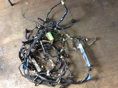
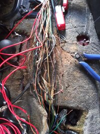
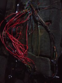
Now the fact I had to pull fuses to get it to run tells me there is a short making the PCM go crazy so I started with sp306 to see if something was going wrong there since it is associated with the LGM, uppon pulling up that flap the shit was melted so I cut the carpet from the fusebox to sp306, I dont care the carpet is under the seat and bad anyways, I found that whole bundle of wire and what I think is windhield fluid line melted together, so I went to work cutting out the old and splicing in new wire ( see pics below.. warning didn't color code since it wasn't even a foot of wire) while doing it sp306 fell off completely so I figured just splicing the light blue, blue white, tan, brown, and orange wires togeather would act as "sp306" and I believe I have everything wired up correctly but I still get no communication to or from the LGM and when putting the key in and turning it on the dash will say driver1 then after a few it says unknown driver and I lose all gauges but speed and rpm.

So after researching I find out the light blue wire from sp306 is to the LGM but if it can't communicate with it something is wrong with the wire or the module, now what I'm asking for is what the wiring path from the connector at the liftgate wiring harness to sp306? My problem is in that bundle there are three wires one of which is the LGM fuses and one of which is to the door chime fuse but the third one I can't find what it has continuity to since none of the fuses beeped at me (might be to the sunroof forgot I had it pulled since I have no sunroof) and since none of the light blue wires had continuity with the harness on the body side of the liftgate harness I am stuck, can anyone help?
 

Attachments

  • 20191115_155307.jpg
    20191115_155307.jpg
    776.3 KB · Views: 48
  • 20191115_181840.jpg
    20191115_181840.jpg
    225 KB · Views: 46
Last edited:

TJBaker57

Member
Aug 16, 2015
2,900
Colorado
Have you any wiring diagrams? They can be downloaded from Moosemans link in his signature.....


That is where I would start familiarizing myself with what wires are what, though they will generally not tell you the path by which they get from point A to point B.

I have no direct experience with the liftgate module wiring but I have read that there is a frequently trouble spot around the top of the liftgate where the wire harness flexes as the gate is opened/closed. Have you checked that out yet?
 
  • Like
Reactions: 808 and mrrsm

Mooseman

Moderator
Dec 4, 2011
25,343
Ottawa, ON
Aye caramba! What a mess indeed! You did, however, a lot of the legwork to get it fixed.

Have you checked the continuity from the LGM to SP306? Have you checked for broken wires in the liftgate wiring boot? What about the origin of what may have caused the melted wiring?
 
  • Like
Reactions: 808 and mrrsm

TJBaker57

Member
Aug 16, 2015
2,900
Colorado
A second thought.... I'm a big fan of those bluetooth (or wifi) code readers that connect to your phone. Cheap ones can be had for less than $20 and better ones for around $50 or $60 I think. For someone working on their own vehicles it's money very well spent.
 

Mooseman

Moderator
Dec 4, 2011
25,343
Ottawa, ON
And with one of those, you can get an Android app called Car Gauge Pro that will read all codes so it might help you pinpoint what is working or not like the LGM.

It's also possible that with that mess of shorts that the LGM or other modules got fried.
 

powerkane

Original poster
Member
Nov 17, 2019
7
mi
I have to be to work soon but I want to reply lol... The 2 bits of info is where does the connector from the lgm run to sp306 the left or right side of the vehicle (the path) and where am I checking the continuity at?

Have you any wiring diagrams? They can be downloaded from Moosemans link in his signature.....
I did download them(ty btw moose) and look at them but I can't tell if the wore goes from the connector to sp306 or connector fusebox then sp306?


Have you checked the continuity from the LGM to SP306? Have you checked for broken wires in the liftgate wiring boot? What about the origin of what may have caused the melted wiring?
I did stick the probe in the connector and then probed all 3 wires no continuity idk if someone that has an 02 can probe sp306 and fusebox or connector to fusebox? tell me if that's the connection or what, for what caused it idk


A second thought.... I'm a big fan of those bluetooth (or wifi) code readers
I have one but I bought a 150 dollar scan tool can't remember the name of it and I could communicate with everything but the lgm aka I could read/control all modules but the lgm


It's also possible that with that mess of shorts that the LGM or other modules got fried.
that is what I thought but idk what to check for continuity for from the connector to sp306 idk the wire path
 
Last edited:

Mooseman

Moderator
Dec 4, 2011
25,343
Ottawa, ON
Like I mentioned, the liftgate boot is a common place where wires break. I'd check for continuity right from the LGM connector to SP306 as well as the others. Should also check for shorts to ground and to other wires since you had one spot of burnt wires, there could be more. I don't know the paths of the wires. With the schematics, you should be able to check them all. The databus wires (SP306) should not have any shorts or continuity to anything else.
 
  • Like
Reactions: mrrsm

powerkane

Original poster
Member
Nov 17, 2019
7
mi
I'd check for continuity right from the LGM connector to SP306 as well as the others.
that's the thing the wire I have going to "sp306" is coming from the fuse box idk if this is correct can someone probe their wire from the Lgm connector to the fusebox for continuity? if there is then i have it set up right and there is a break in the light blue line to from the splice pack to the fusebox to the connector
 

mrrsm

Lifetime VIP Donor
Supporting Donor
Member
Oct 22, 2015
7,727
Tampa Bay Area
Here are some Wire Color- Coded Diagrams of the GM Class 2 Network System for GMT360s that includes the LGM Circuit.

90SCORVETTESPLICEPACK.pngBCM2004DIAGRAM.jpegTBCLASS2NETWORK.jpgTBCLASS2NETWORK2.jpg

This First Video shows how to Check the Ground (ALL Black Wire Splice Pack) SP201 for Good Connection to the SUV Body and an explanation of all the items it services:


The Next Video shows how to Take Down the Entire Network on the (+) Positive 0-7 Volts DC Side of the Class 2 Network and allow you to Trace through each one and Bring On-Line One Module at a Time. Having a Tech 2 and an Oscilloscope would certainly be handy ...but NOT absolutely necessary... if you carefully use a Lighted Pin Probe to check for Power and Grounds and use the "Bent Wire Technique" for checking each connection as shown here. The Network should come alive to alert you which Module is the offending one as soon as you Pin Connect it to Power and the Network Crashes:


As emphasized by @Mooseman... The LGM can go sideways if the Wiring Bundle passing through the Tail Gate Conduit has work-hardened, broken wires hidden inside (see attached images). The class 2 Network can Go Down... either from getting Shorted to Ground...or ...getting Shorted to 12 Volts DC:

s-l1600E.jpgLGM.jpgLGMTHRUTHEBOOTWIRING.jpgLGMTHRUTHEBOOTWIRING2.jpgLGMTHRUTHEBOOTWIRING3.jpg


If it Helps... There is much more detailed information, Images and PCM Pin-Out Diagrams available at THIS Link... Mostly on Page 1:

 
Last edited:
  • Like
Reactions: Mooseman

mrrsm

Lifetime VIP Donor
Supporting Donor
Member
Oct 22, 2015
7,727
Tampa Bay Area
Oh... and if it were me... I'd be looking to get my hands on a Used Body Harness in order to sidestep that Fire-Bugged Rats Nest that lives inside your SUV....if for no other reason than to chop out the matching section of the involved Burned Area you have to deal with... And Solder in and Weather Heat Shrink Insulate each of them ...one Color-Number Matched Wire at a time:

If it helps... Check out THIS one and others,too for the Right One... Available on eBay right now:


2005SUVBODYWIREHARNESSBUNDLE.jpg
 
Last edited:
  • Like
Reactions: Mektek and Mooseman

budwich

Member
Jun 16, 2013
2,047
kanata
so, lots of stuff has gone down and it sounds like you are almost there. The "holdup" is the LT BL going from the "splice pack" to the LGM. The simple check is to go to the connector at the LGM, locate the LT BL wire in the connector. Disconnect the cable connector from the LGM. Take your meter, and measure resistance to a "known" ground on the LT BL wire. What is it? Now do the same measurement going toward the LGM (ie. the pin that the LT BL would have been connected to when plugged in. What is that measurement? Go from these results.
 

powerkane

Original poster
Member
Nov 17, 2019
7
mi
Ok so I found out part of the problem I had the light blue lgm connector wire wired to the wrong light blue coming from the bundle I found continuity between the connector and my "sp306" it is now wired correctly I no longer have the unknown driver issue just no communication to the lgm with the scan tool still, I might have the lgm fuse wire and door chime wires backwards will test my thought soon, but anyway now that I have continuity to the plug I'll let u know the tailgate has been replaced with a newer model tailgate but b4 I rule out the module I wanna test those other 2 wires by swapping them first
 
Last edited:

mrrsm

Lifetime VIP Donor
Supporting Donor
Member
Oct 22, 2015
7,727
Tampa Bay Area
Here is an image of the Three LGM Connectors with the various Colored Wires spread out for easier Position Identification:

LGMCONNECTORSCOLORWIRES.jpg
 

powerkane

Original poster
Member
Nov 17, 2019
7
mi
no luck with swapping the wires now I have to search for my original LGM and harness to test but as of right now I'm comfortable with the fact I have gauges again just no tailgate control I can always manually lock the tailgate since I have the cover off atm.

as for buying that harness that's half the price I paid for the SUV LOL
 
Last edited:

mrrsm

Lifetime VIP Donor
Supporting Donor
Member
Oct 22, 2015
7,727
Tampa Bay Area
Yes... Zoom in on the Attached Image below. There is fairly good Visual Information to be seen in the Lower Right Quadrant of THIS Class 2 Network Color Wiring vs. Module Connector Wiring Diagram indicating that the LGM Connector(s) C2 and C3 are attached to the Network accordingly, with variously Colored Wires being specified for Class 2 Network Communications (Note that the LGM Connector C1 is NOT Mentioned or shown thereon, so it may NOT have any Class 2 Network Connections; probably due to it working the Motor Driven Rear Windshield Wiper Unit).

Please check your Downloaded GM OEM Service Manual Chapters again for more specific information about these Wiring Diagrams and their Connector Layouts-Pin-Outs for more precise views. You might have to bounce around through seemingly unrelated Chapters to find them... but they are usually shown along with many other images of each of the different types of Connectors for the various Modules involved:

COMPUTERDATALINESYSTEM.jpeg

As far as the Expense of obtaining a Used Body Harness goes... You really should consider that what can be seen in those two images you posted indicates the mere symptoms of having a larger problem unseen right now of Power Shorted After-Market -Sub Standard Wiring that could ignite portions of your interior and cause a Fully Involved, Catastrophic Fire.

Such an event would ultimately prove much more than a mere inconvenience if things got out of control and your SUV winds up Burning Down to the Rims on the side of the Road. You can be certain that you might be discounting this possibility at the risk of your own peril (along with any unfortunate Passengers who happen to be on board).
 
Last edited:
  • Like
Reactions: 808

Mooseman

Moderator
Dec 4, 2011
25,343
Ottawa, ON
Another option would be to find one at a pick-n-pull if you have one nearby. Then you would also see the routing.
 
  • Like
Reactions: mrrsm

powerkane

Original poster
Member
Nov 17, 2019
7
mi
BTW ty to everyone for quick responses and helping me get through this mess, sometimes it takes other people looking at it to work it out lol.

Another option would be to find one at a pick-n-pull if you have one nearby. Then you would also see the routing.
I live in a small town we got a trailblazer in the junkyard that I pretty much took all I could off it but its a newer model and the harness is different sp306 had like 8 wires on it or something like that lol
 
Last edited:
  • Like
Reactions: mrrsm

powerkane

Original poster
Member
Nov 17, 2019
7
mi
Ok so I think i got it all sorted now it was a combination of 2 things
1. Burnt wires spliced out with new ones
2. The connector in the back pretty much fell off when I tugged on it lightly (I'm guessing that's why I had no continuity when I tried to do the light blue wire by myself but did with help) the only thing holding it on was the brown wire so spliced new ones in

As far as I'm concerned my problem has been solved all I need to do is clean up the wires with some of that split tube sleeving.


Keyfobs work and now I have to figure out why the rear windshield wiper isnt working im guessing it's seized up since the arm was rusted to crap
 

mrrsm

Lifetime VIP Donor
Supporting Donor
Member
Oct 22, 2015
7,727
Tampa Bay Area
Please consider getting an "Automotive Grade Color Wire Bundle" if you need to continue replacing any damaged strands here and there. The difference between THIS kind of wire and 'Standard Electrical Wire' is Very Remarkable:

(1) High Heat and Temperature Resistance to Breakdown under Stress.
(2) Bonded Insulation that will NOT separate from the Internal Wire Strands.
(3) PURE COPPER vs.CCA (Copper Clad Aluminum) for Greater Safety and Electron Flow.
(4) Ten Colors to Better Color Match Replacement Wiring ...in 25' Sections.
(5) Very Inexpensive ($33.00 per Bundle) for the Quality and Reliability Obtained.


VARICOLORAUTOWIREBUNDLE.jpg
 
  • Like
Reactions: Blckshdw

808

Member
May 5, 2022
209
Georgia
Thank You Sir! Yet again, I salute you for your in depth explanation and direction surrounding these anomalies!!!

Your Mentorship In This Forum Has Been *EXTREMELY* Helpful.

I'm presently in the midst of the exact condition (*&Corresponding 2008 4.2L Configuration*) depicted from the video you linked earlier in this post from Mr. Robinson @ RobinsonsAuto.

This is the first time I've ever *****Had***** to dig so deeply into the communications network, as this is the only instance where I've performed a comprehensive "disturbance" of each and every aspect of essentially every square inch of the 2008 4.2L Trailblazer Lt.

If the Trailblazer Depicted in this video was equipped with a ^Driver Information Center^, I'm certain that this condition would have been accompanied by an "UNKNOWN DRIVER" readout from the cluster.

What I'd like to ask you about specifically is included in my following post.
 

808

Member
May 5, 2022
209
Georgia

*
What I'd like to ask you about specifically is your direction here:
*
(Which I'm Very Excited About, As I Do -Not- Have a Tech 2, or Module Capable Scanner)


^When you said^:

"use a Lighted Pin Probe to check for Power and Grounds",


My Inquiry:

How are you instructing that the Pin Probe be exactly introduced into the diagnostic chain?

?Am I Understanding? ?That The Pin Probe:

*Should Be* Clamping to the Purple Class 2 Network Wire,

& Then Selectively / Exclusively Paired With Each Module @ JX 205 Splice Pack?


Thank You For All Of Your Prolific Contributions To This Community.
Sincerely,
808
 

Attachments

  • ThankYouMrrsm.jpg
    ThankYouMrrsm.jpg
    195.7 KB · Views: 3

mrrsm

Lifetime VIP Donor
Supporting Donor
Member
Oct 22, 2015
7,727
Tampa Bay Area
In my suggestion that you can use a Lighted Probe, it would strictly be tried on each individual Module Colored Wire connecting them to the Splice Pack...for Continuity. But consider that THIS is a Very Hit Or Miss Method.

In the absence of actually being able to SEE the PWM (Pulse Width Modulation) CHANGING ON SCREEN ...showing up as Moving Blocks of Squiggly Lines, Oscillating in the Vertical Scale in the Range of 0 to 7 Volts-Over-Time that is standard to all Class 2 Networks... these signals CANNOT be Visualized without using a "GYMKO" Tech 2, or an Inexpensive Oscilloscope or a Graphing Multi-Meter such as the Snap-On MT2400.

ALL other DMM Devices just AVERAGE THE VOLTAGE INPUTS... and thus, they CANNOT respond fast enough to show these rapidly switching, Tiny Square Wave Events as they are occurring. In contrast, the "GYMKO" Tech 2 becomes useful here because it is a GENUINE GM BI-DIRECTIONAL SCAN TOOL that is capable of *PINGING* either all or singly. any and all Modules on the Class 2 Network at any time and allow the Mechanic to SEE whether any or all of them are either in an ACTIVE or an INACTIVE state on the Small Deep Blue Colored Tech 2 Screen.

Getting back to the "HIT or MISS Method"... Pulling out the "Toothy Metal Grounding Bar" of the Central Meeting Points (at the Splice Packs that are located under the Left Under Dashboard and under a Carpet Flap of the Right Rear Passenger Seat) and then by following Will Robinson's Method specified in his Famously Instructive Video, it will allow you to Bring Each Module Back On Line....One at a Time... BUT... Without having any of the other Diagnostic Tools mentioned above, You won't have a clue as to whether or not any particular Module is THE One at Fault.

Peppered all over GMT Nation...There are Threads in which I've suggested the use of various types of Oscilloscopes. Some are Fairly Expensive, while there are others that are Relatively Cheap and Affordable. But you need to realize that without possessing and using these unique tools capable of "Slicing Voltage vs. Time" into EXQUISITELY SMALL SEGMENTS... the Average Mechanic will be at a Total Loss with trying to figure out WTF? is REALLY going on.

There are so many things at play in Modern Autos, Trucks and SUVs that require and use Electricity and thus, ALL of these components and systems lend themselves to being revealed in a dazzling array of Diagnostic Methods using Oscilloscopes. I'm suggesting that You check THESE out over on Amazon and realize that IF You want to be a True Diagnostician, You'll need to Arm yourself with the Proper Tools for any such analyses:


NOTE:

If you want to know and learn more on this topic, spend some time perusing THIS Thread in which these ideas about using Oscilloscopes in all their Glory have been more thoroughly exemplified ... and demystified:

 
Last edited:
  • Love
Reactions: 808

808

Member
May 5, 2022
209
Georgia
In my suggestion that you can use a Lighted Probe, it would strictly be tried on each individual Module Colored Wire connecting them to the Splice Pack...for Continuity. But consider that THIS is a Very Hit Or Miss Method.

In the absence of actually being able to SEE the PWM (Pulse Width Modulation) CHANGING ON SCREEN ...showing up as Moving Blocks of Squiggly Lines, Oscillating in the Vertical Scale in the Range of 0 to 7 Volts-Over-Time that is standard to all Class 2 Networks... these signals CANNOT be Visualized without using a "GYMKO" Tech 2, or an Inexpensive Oscilloscope or a Graphing Multi-Meter such as the Snap-On MT2400.

ALL other DMM Devices just AVERAGE THE VOLTAGE INPUTS... and thus, they CANNOT respond fast enough to show these rapidly switching, Tiny Square Wave Events as they are occurring. In contrast, the "GYMKO" Tech 2 becomes useful here because it is a GENUINE GM BI-DIRECTIONAL SCAN TOOL that is capable of *PINGING* either all or singly. any and all Modules on the Class 2 Network at any time and allow the Mechanic to SEE whether any or all of them are either in an ACTIVE or an INACTIVE state on the Small Deep Blue Colored Tech 2 Screen.

Getting back to the "HIT or MISS Method"... Pulling out the "Toothy Metal Grounding Bar" of the Central Meeting Points (at the Splice Packs that are located under the Left Under Dashboard and under a Carpet Flap of the Right Rear Passenger Seat) and then by following Will Robinson's Method specified in his Famously Instructive Video, it will allow you to Bring Each Module Back On Line....One at a Time... BUT... Without having any of the other Diagnostic Tools mentioned above, You won't have a clue as to whether or not any particular Module is THE One at Fault.

Peppered all over GMT Nation...There are Threads in which I've suggested the use of various types of Oscilloscopes. Some are Fairly Expensive, while there are others that are Relatively Cheap and Affordable. But you need to realize that without possessing and using these unique tools capable of "Slicing Voltage vs. Time" into EXQUISITELY SMALL SEGMENTS... the Average Mechanic will be at a Total Loss with trying to figure out WTF? is REALLY going on.

There are so many things at play in Modern Autos, Trucks and SUVs that require and use Electricity and thus, ALL of these components and systems lend themselves to being revealed in a dazzling array of Diagnostic Methods using Oscilloscopes. I'm suggesting that You check THESE out over on Amazon and realize that IF You want to be a True Diagnostician, You'll need to Arm yourself with the Proper Tools for any such analyses:


NOTE:

If you want to know and learn more on this topic, spend some time perusing THIS Thread in which these ideas about using Oscilloscopes in all their Glory have been more thoroughly exemplified ... and demystified:

Thank You For Your Very Prompt & Surgical Reply!!!! Your expounding on your previous explanation is quite helpful. I Do ***VERY MUCH*** appreciate your time and attention on this matter of inspection and observation.


Surely confirming now that I further and firmly grasp the "delicacy" and "quickness" of these signaling events.


Yes Sir, it would appear that necessity does *inexorably compel* me to exact along this thusly apportioned line of developmental Diagnosticianship :wink:

Thank you for all of your provisional compass explanations in this theater. It is vast.

I will examine the demystification thread and forge ahead to appropriate the appropriate instrumentation for these analyses.

Sincerely,
808
 

Forum Statistics

Threads
23,328
Posts
637,959
Members
18,531
Latest member
jvest

Members Online