'06 engine ring/bearing/valve job

rchalmers3

Original poster
Member
Jul 11, 2020
207
Irmo, SC
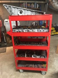
As suggested, I'll post up some photos of my progress on the creation of a fresh donor motor for my daughter's 2006 Trailblazer. I had mentioned previously that I had bought her a fixer-upper, with a nice interior, exterior and newer tires. It had some engine noise that turned out to be wiped out rod bearings on cylinders #2 and #4. The motor runs and can move the vehicle around, so I'll leave it there until I prepare a replacement.

I found a local guy who is way ahead of me on the 4.2 Vortec motor fan club. He has about 35 of these summer trucks: (summer better than others). I was jealous and disappointed, 'cause I thought I would be the first in my area to engage in a long term operation focused on these vehicles/engines. I gave him $600 and brought home a 2006 engine. He said it was a runner and would have installed it as is, as it is his practice to replace vs. repair.

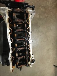
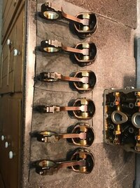
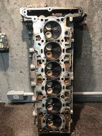
I brought the motor home and disassembled it. I'm pleased to report that the motor is a good candidate for rings, bearings and a valve job. The cross hatching in the bores are still present, there is very minimal piston scuffing, and the rod and main bearings look very good. The oil rings are very stuck in their grooves, so I'm glad to have gone ahead with the refreshment of the engine vs simply installing it.
 

Attachments

  • IMG_0085.jpg
    IMG_0085.jpg
    60 KB · Views: 28
  • IMG_0082.jpg
    IMG_0082.jpg
    91.6 KB · Views: 28
  • IMG_0084.jpg
    IMG_0084.jpg
    101.8 KB · Views: 28
  • IMG_0086.jpg
    IMG_0086.jpg
    97.5 KB · Views: 27
Last edited:

rchalmers3

Original poster
Member
Jul 11, 2020
207
Irmo, SC
The oil pump pick up screen had the expected accumulation of flakes of coked carbon chips. Nothing that was of any concern. It did however have a single, large, long metal chip. It appears to be a long, continuous coil of (non-ferous) aluminum. I suspect it was from the block construction, and had resided in the pick up screen since day 1. What do you think?
 

Attachments

  • IMG_0081.jpg
    IMG_0081.jpg
    49.1 KB · Views: 13

rchalmers3

Original poster
Member
Jul 11, 2020
207
Irmo, SC
My next step is to embark upon creating a relation with an automotive machine shop. I have contacted one in my area and will drop off the engine parts for cleaning, measuring and machining. I'll post up more about the experience and details after I have dealt with them and have formulated a plan of approach. BTW, I broke one exhaust manifold bolt and 5 head bolts on disassembly. Guess I'm golfing at par.
 

mrrsm

Lifetime VIP Donor
Supporting Donor
Member
Oct 22, 2015
7,731
Tampa Bay Area
I agree entirely with your approach to the Engine Reconditioning. As for the Aluminum Shards that you found... if the Thrust Bearing(s) Half Moon section fitted at the 5th Journal was worn Razor Thin ...or missing entirely during your disassembly, this might allow the Crankshaft enough freedom to move and shift fore and aft inside the Engine Block.

This movement might have allowed the Counterweight Throws on the Crankshaft to make direct contact with the inner boss areas of those Mains Buttresses and grabbed or shaved off the residual Aluminum Shards. This will be easy enough to determine if you find matching damage on the Mains Buttress flanks... or dismiss the idea if not.

This excessive motion can also cause cracks in the Flex-Plate Bolt Pattern around the Aft Crankshaft Bearing Journal Holes for the TTY Bolts. Now that you have disassembled everything... All of these areas will be very easy to examine and look for anything untoward.
 
  • Like
Reactions: rchalmers3

rchalmers3

Original poster
Member
Jul 11, 2020
207
Irmo, SC
Thanks for the heads up.
The crank end play with rods removed was what was anticipated, between zero and whoa, prolly .04-.08 thou. Given that observation I did not investigate the thrust bearings. I pulled and gave a visual to a few of the main caps.

If the end play went away, I'd suspect the shavings would be an accumulation of fine powder flakes, not a long, single curl like the one pictured.
 
  • Like
Reactions: mrrsm

gmcman

Member
Dec 12, 2011
4,656
Awesome thread, thanks for sharing the progress.

I'm very tempted to start building a motor for my 02 if by chance she ever starts to head down that road.
 

mrrsm

Lifetime VIP Donor
Supporting Donor
Member
Oct 22, 2015
7,731
Tampa Bay Area
I wonder if the Original Owner cross-threaded the Oil Plug Hole in the Crankcase and had to ream it out and install either a Heli-Coil or better yet, a TIME-SERT repair to it.

If so, that action may have left those shards in the bottom of the Pan waiting to get swept along with the Oil Flow getting sucked into the Oil Pick Up Screen where they eventually lodged.

Again... Very EZ2 investigate with the Crank-Case sitting on your Parts Caddy.: :>)
 

TollKeeper

Supporting Donor
Member
Dec 3, 2011
8,053
Brighton, CO
So are you trying to put a 2006 engine in your 2008? Im really confused now...

Based on your other thread, it looks like you realized it wont work, and are looking for a new/another engine.

I have a question thou. I know on the LS engines, you can remove the reluctor ring, and install the needed ring. Is that not an option on the LL8?

Edit: I admit I know little on the LL8 engine, just trying to learn.

Edit2: Upon some google searching it looks like the reluctor ring is in the middle of the CS vs the end of the CS that the LS engines have. So you could just replace the crankshaft with the one needed with the correct reluctor ring?
 
Last edited:
  • Like
Reactions: rchalmers3

rchalmers3

Original poster
Member
Jul 11, 2020
207
Irmo, SC
So are you trying to put a 2006 engine in your 2008? Im really confused now...

Based on your other thread, it looks like you realized it wont work, and are looking for a new/another engine.

I have a question thou. I know on the LS engines, you can remove the reluctor ring, and install the needed ring. Is that not an option on the LL8?

The confusion is mine.... Allow me to attempt clarification.

The target vehicle I acquired for a donor engine is a 2008. However it is equipped with a 2006 driver door. I did not notice that until it was too late.

I bought a 2006 engine for a replacement for the DOOR year model! Currently that engine, the one photographed in this thread is at the machine shop. It is the basis for this post and it looks like an excellent candidate for rings, bearings and a valve job. I'll post more on that engine as it moves through the machine shop process. That may be some weeks as the shop was very full of work, which is a good thing I presume.

Meanwhile, I bought a rolleThus I will have some work to do while waiting to reassemble the 2006 motor.

I intend to collect a small herd of these vehicles as I am enamored with the platform. I don't have a lot of yard space, therefore I am limited to having only a handful here at one time. The rebuilt 2006 motor will be something I'll restore for a future purchase.

Regarding the crank position sensor, I'm new to these motors as well, but a quick peek at the 2006 motor provided me an opportunity to understand that detail. The 2006 crank (7x reluctor) has seven indents cast into a crank lobe, on #5 cylinder I believe. So there would be no swapping the signal generation without a crank swap, and I'm not sure that is possible, or even worthwhile. Given the current availability of these engines, I resorted to finding a running replacement. When I get the existing engine out of the 2008, I'll disassemble it as well and let you know what the differences are.

Hopefully this explanation has cleared up the confusion I created.
 
Last edited:
  • Like
Reactions: TJBaker57 and mrrsm

mrrsm

Lifetime VIP Donor
Supporting Donor
Member
Oct 22, 2015
7,731
Tampa Bay Area
Answering the Question here in your "Build Thread" that you just posed over in your "Intro Thread" regarding New Parts, Sealants, Tools with OEM Part Numbers & Factory Packaging Information:

Page 1 displays Sub-Lists of GM 4.2L LL8 Engine-Lubrication-Tools Descriptions and Parts with OEM Numbers:

https://gmtnation.com/forums/threads/the-85-000-00-gm-4-2l-engine-repair.14423/

GM 4.2L LL8 New Engine Parts with Box End Images and OEM Packaging Numbers (5 Pages.... In NO Particular Order):

https://www.flickr.com/photos/126111508@N07/albums/72157671179967478/page1
 
Last edited:
  • Like
Reactions: rchalmers3

rchalmers3

Original poster
Member
Jul 11, 2020
207
Irmo, SC
A two week update on this thread: The 2006 engine parts are still at the machine shop. No progress report from them yet. I should prolly call them.

I bought a rolled 2008 with a good drive train, brought it home and stripped it to collect parts, then hauled the crushed body to the metal recycler . I now have an extra rolling chassis..... I have some ideas about what I can use it for...

I removed the 2008 target vehicle engine and transmission. Good thing: I dropped the transmission pan to contain the mess and found lotsa metal dust collected around the pair of magnets. I'll be rebuilding that, while stuffing the used motor straight in. I confirmed that both engines have the high number of reluctor teeth on the crank by peeking in the sensor bore, so I will be avoiding that potential error. All other potential errors await!

I took both engines out bit by bit, component by component. But on the host motor removal, I ultimately had to lift out the engine with the transmission mated, due to a single converter bolt that I rounded. I made it easier by shortening the assembly: separating the transfercase beforehand. I mention this because I'm thinking of refitting the used engine and rebuilt transmission mated, like I removed them, but with the cooler and fuel lines and wire harness all pre-laid onto the assembly. I think this will be a solution to that mess of bracketry, hard piping, wire harnesses and vent hoses all routed behind the head and under those top two bell housing bolts. What say you?
IMG_0092(1).jpg
The transmission rebuild is gonna slow down the progress. I'll post another progress report in a few weeks, regardless of status.
 

mrrsm

Lifetime VIP Donor
Supporting Donor
Member
Oct 22, 2015
7,731
Tampa Bay Area
Not sure which "Cooler Lines" you mentioned... but the only consideration to be mindful of during final assembly are those two Damned Aluminum Brackets holding the Cross-Firewall Aluminum Heater Hose Pipe that will need to be installed during the final Engine to Transmission Mate Up.

Doing so will solve the problem of having the extreme difficulty of working them in later on as an afterthought AND have to deal with limited access to the Two Top 15mm Bell Housing Bolts to the Engine Block behind the very tall Valve Cover-Engine Head.

If nothing else, but for the sake of the GM ASE Mechanics' sensibilities at the Dealerships, way back in the late 1990's, Mr. Ron Kociba and his GM Atlas Engine Design Crew should have included Secure Bolt-In Access Panels through the Transmission Hump that would have made Engine to Transmission separation in those hard to reach areas so much easier.
 
Last edited:
  • Like
Reactions: rchalmers3

m.mcmillen

Member
Apr 29, 2016
554
Wisconsin
They’re not that hard to access. Remove the transmission crossmember and let the whole assembly tilt down. Then, get a 3 foot extension and stick a 15mm universal on the end and take the bolts out.

Look around and you can find a 3 foot extension that is 1/2 inch female and 3/8 male and then use a 1/2 inch impact to zip those bolts right out.

The access cover reminds me of a GMC 8000 truck with an 8.2 Detroit engine. The engine was so crammed in that there was no room for the pushrods to come out, they hit the body of the truck. They actually did put access covers in the floorboard to get the pushrods out.
 

mrrsm

Lifetime VIP Donor
Supporting Donor
Member
Oct 22, 2015
7,731
Tampa Bay Area
Indeed... and Thanks again Mac to your Prior Post on this using this Technique...I was able to get one of those Really Long Extensions from an alternative source. Back in 2015, just before I got hurt and was in dire need of back surgery, I used a different combination of 3/8" Extensions with 1/2" Adapters and a 1/2" Milwaukee Pneumatic Right Angle Ratchet when pulling a 4L60E R&R.

They were so damned long, that their combined weight caused them to curve downwards over the top of the Transmission, making controlling the 15mm Socket interface One Big PITA. During that one week period...I developed such a "Six Pack" of stomach muscles from trying to hold myself up from a prone position over the back of the Transmission that a Cat Couldn't Scratch them. So being able to reach under the Transmission Hump Carpet to unbolt Access Covers and easily R&R those 15mm Fasteners would have pleased me to no end.
 
Last edited:
  • Like
Reactions: rchalmers3
Dec 5, 2011
576
Central Pennsylvania
K series Chevy trucks had such a panel... from directly above the tail of the transfer case to the output coupling from the transmission. I couldn't ~quite~ reach the forward output shaft, but could easily get to the tcase shifter and its mount. I could also completely disconnect the tcase from the tranny without any difficulties.
 

rchalmers3

Original poster
Member
Jul 11, 2020
207
Irmo, SC
They’re not that hard to access. Remove the transmission crossmember and let the whole assembly tilt down. Then, get a 3 foot extension and stick a 15mm universal on the end and take the bolts out.

I have long extensions, both 3/8" and 1/2", and have now removed a few of these engines that way. Sometimes the thrill is loading up the extension and feeling the torsion go "pow" when the bolt breaks loose. The two points that bother me about doing it this way are the severe deformation done to the motor mounts while dropping the rear cross member, and there are still those pesky loom attachment rings cluttering up the access to those top bolts. Those are not a big deal, but I'd like to do better.

I'm pretty sure I'm going to try the installation as I mentioned. I'll let you know how it goes. You guys might laugh at me: I work alone and on the ground. No lift and no technician "B" to assist.
 
  • Like
Reactions: mrrsm

Mooseman

Moderator
Dec 4, 2011
25,344
Ottawa, ON
You guys might laugh at me: I work alone and on the ground. No lift and no technician "B" to assist.

No laughing here. I did mine mostly by myself in my driveway. And I was able to get the bolts off/on without extensions, using a ratchet wrench but I dropped the engine onto the frame. Hands came out looking like I found that feral cat that lives in all engine bays.
 

rchalmers3

Original poster
Member
Jul 11, 2020
207
Irmo, SC
No news on the engine at the rebuilders yet. I picked up the hot tanked parts a few weeks ago. They said they were just about to tackle the block, crank and head.... I guess I don't know what "about to" means.

The daughters car is coming along nicely. The transmission is rebuilt, and the engine and transmission are fitted. It starts and runs, but I don't yet have the transfer case and driveshafts installed. I found out that I'm no longer young and dumb enough to bench press a transfer case into place, while engaging the shaft splines and dodging around the obstacles under there. I did fit the motor and transmission as a mated assembly as I said I'd like to try to do. It went Ok, but I'm not certain it was better, faster or easier. Considering I have found out that I can no longer press a hundred pounds of transfer case, I'll prolly not go that direction again, at least on 4wd. But it was sure nice fitting so many parts and sorting out all the hard piping and cable routing while the engine was on a stand.

I a previous lifetime I booty fabbed a transmission jack that dropped into the rotational head on my floor jack. I may build one again, to support a either 2wd tranny or a tranny transfer case assembly. If you guys have any suggestions on something you use that works, I'm all ears!
 

rchalmers3

Original poster
Member
Jul 11, 2020
207
Irmo, SC
Any tips on where to find good quality gaskets for the head and exhaust manifold? I'd like to use quality MLS gaskets in those positions. It's for a 2006 engine.

I'll use a $80 gasket set for all the other sealing pieces.
 

mrrsm

Lifetime VIP Donor
Supporting Donor
Member
Oct 22, 2015
7,731
Tampa Bay Area
eBay has EXACTLY what you need...already imagined, designed, welded, chained up... and ready to go:

$55.00.. WITH Free S&H...AND a 'MAKE AN OFFER' ... Option:


FLOORJACKTRANSUPPORT1.jpgFLOORJACKTRANSUPPORT2.jpgFLOORJACKTRANSUPPORT3.jpgFLOORJACKTRANSUPPORT4.jpgFLOORJACKTRANSUPPORT5.jpgFLOORJACKTRANSUPPORT7.jpgFLOORJACKTRANSUPPORT8.jpgFLOORJACKTRANSUPPORT9.jpg
 
  • Like
Reactions: rchalmers3

rchalmers3

Original poster
Member
Jul 11, 2020
207
Irmo, SC
That's ALMOST perfect! thanks for digging that up.

It would be perfect if it had a second tilt axis: side to side. But for the price..... I'll go confirm the diameter of the jack head hole. I may be in business! Thanks again!

Rick
 
  • Like
Reactions: mrrsm

mrrsm

Lifetime VIP Donor
Supporting Donor
Member
Oct 22, 2015
7,731
Tampa Bay Area
This is the Complete Kit you will need... The Exhaust manifolds that run the gamut from the 2002 to 2009 Trailblazers and Envoys are NOT Identical:


DORMAN-EM-674-990A.jpg
 
  • Like
Reactions: rchalmers3

rchalmers3

Original poster
Member
Jul 11, 2020
207
Irmo, SC
I use Felpro on every head gasket I do and have never had a issue.
Thanks, I looked at Felpro and have used them for decades, but those exhaust manifold gaskets, with the waffle metal skin over asbestos.... I'm not a fan. I'd much prefer a MLS (multi layered steel) gasket with the dimple bead that crushes.

Rick
 

rchalmers3

Original poster
Member
Jul 11, 2020
207
Irmo, SC
This is the Complete Kit you will need... The Exhaust manifolds that run the gamut from the 2002 to 2009 Trailblazers and Envoys are NOT Identical:

I'm not needing a manifold. Mine just needed to be flycut on the mating surface is all.
Too bad the dealer does not sell the good stuff any longer. I may be using a Felpro kit, as the Mahle kits with MLS gaskets go for $400!

Rick
 

rchalmers3

Original poster
Member
Jul 11, 2020
207
Irmo, SC

rchalmers3

Original poster
Member
Jul 11, 2020
207
Irmo, SC
eBay has EXACTLY what you need...already imagined, designed, welded, chained up... and ready to go:

$55.00.. WITH Free S&H...AND a 'MAKE AN OFFER' ... Option:

View attachment 96775View attachment 96776View attachment 96777View attachment 96779

The results are in: This purchase was a miss. The issue is the total height of the device once it's mounted on your jack. Unless you can raise the vehicle until the bottom of the frame is about 36" above ground, you will find that you won't be able to roll the transmission and jack under the vehicle. I ended up sliding the transmission under the vehicle first, then used a large amount of cribbing to raise the trans. Then I slid the jack under the transmission and continued the install.

As a side note, I had to modify it to have it fit my Harbor Freight jack. No biggie, just 30 minutes of cutting, grinding, then drilling the bottom plate to accept a shoulder bolt. That modification actually saved me about 2" in assembled height. If I use this tool again, I will add features to the vertical pieces that contact the pan bolt lip. They need to wrap around the edges of the pan to limit fore/aft slippage of the trans while it's resting on top of the adapter.

Rick
 

rchalmers3

Original poster
Member
Jul 11, 2020
207
Irmo, SC
This weeks update: The machine shop did not have tooling to extract the head bolt remnants. I have ordered an extraction kit and will deliver to the machine shop it when it arrives.

Rick
 

JayArr

Member
Sep 24, 2018
504
Mission BC Canada
The issue is the total height of the device once it's mounted on your jack. Unless you can raise the vehicle until the bottom of the frame is about 36"

I have one that looks just like that, it's 5" tall from the jack to the platform, my jack is 4" tall at it's lowest point and the bell housing is about 18" tall with the pan on the floor. That makes the total 27"

I did this two weeks ago. I used some monster 12 ton jack stands that go to 28". They start at about 18" so jack the car up until it's on the jacks at the lowest position. Then build a crib that is 10-12" tall that the jack can sit on, (I used 4x4s and garden ties I had leftover from fencing) it needs an upper surface flat enough for the jack to move laterally, I used plywood. Before you start to lift make sure the rear swivel castors of your floor jack are oriented to pull along strait and parallel. If the floor jack doesn't move on the plywood as you lift then the car will get pulled toward you and the jack stands on the other side will tilt and come off the ground on the outside. I did this at first and noticed before I climbed under, it scared me enough that I'll never make that mistake again!

Put the jack on the crib and start raising the car again, when you get the bottom of the frame rail to about 22" stop and put the car on the stands. Repeat on other side. Any higher and the transmission jack won't reach.

Get under the car and pull the transfer case and then the transmission. There is lots of room underneath at this point, if I was under the tunnel I could sit up straight.

Now with the tranny on the jack stand lowered all the way it still won't come out but I have two floor jacks so I used the other one, on the crib, to jack up one side only, from 22" to 28" and the tranny waltzed right out. I rolled it into the garage and swapped it for the good one and rolled it under then lowered that side of the car back to 22" again and installed the new tranny.

It was an extra hour building the crib and you need two jacks and the 12 ton stands but I did it all myself in the driveway.
 
  • Like
Reactions: rchalmers3

rchalmers3

Original poster
Member
Jul 11, 2020
207
Irmo, SC
Update: I got all the 2006 engine pieces back from the machine shop. These include:

a) The block has the broken head bolts removed, the head alignment dowels removed, and was lightly honed (standard bore)
b) The crank is standard/standard, with a light polish
c) The head has been checked, a single broken manifold bolt removed and valve job with new seals
d) The exhaust manifold has received a fly-cut on the manifold mating surface
e) The oil pan, valve cover, timing cover, girdle and rear main cover were all hot tanked

The machine shop charged me $750 for their effort, plus the valve stem seals. I bought and provided them with the bolt extraction kit. I feel their price was fair, considering the 3 month wait.

The pistons and rods were in great shape. I removed the pistons from the rods, removed the rings and then soaked the pistons in carb-dip to soften/remove the carbon build up. I have a Felpro gasket set, Sealed Power ring set plus rod & main bearings, an OEM exhaust manifold gasket, and OEM rod, main and head bolts. I also have the replacement guide pins (alignment dowels) for aligning the head. I'm waiting on a strip of Plastigauge and some assembly lube.

My intention is to assemble this engine as is, with the solo modification of widening the ring gap to allow for the pressures and heat of forced induction.

Once this engine is assembled, I'll get the 2008 engine disassembled and ready for the machine shop. This may take some time as I have undertaken some carpentry work for a neighbor. The income will provide additional play money.

I'm thinking of turning a spare chassis (sans body) into an engine/transmission test bench. I dunno if It's really needed, but I imagine it would be a great tool for the development of forced induction. Shoot, it would be a good way to run in any engine, racing or otherwise! Have you guys built a test stand for your play with these engines?

Lemme know if you want me to photo document the build. I feel kinda silly documenting a project you must have already done many times.

Rick
 

rchalmers3

Original poster
Member
Jul 11, 2020
207
Irmo, SC
I forgot to mention: The daughters 2008 (with the 2006 Driver door!) is completely operational. The transmission shifts nice, and the engine sounds great. The brakes and tires are 90% new, I put in AC Delco shocks all the way around and recharged the AC. It is the finest car in our humble family fleet, and when this pandemic thing is over, I intend to drive it up the east coast of the US to visit family in New England.

Thank you guys for your interest and support. I hope to contribute to this forum as I have benefited.

Rick
 
  • Like
Reactions: mrrsm

Mooseman

Moderator
Dec 4, 2011
25,344
Ottawa, ON
I'm thinking of turning a spare chassis (sans body) into an engine/transmission test bench. I dunno if It's really needed, but I imagine it would be a great tool for the development of forced induction. Shoot, it would be a good way to run in any engine, racing or otherwise! Have you guys built a test stand for your play with these engines?

Someone else had done this and worked very well. He had stripped it and used it just to test engines. Wasn't that long ago. It couldn't be plated for some reason so he used it as his test bed. I can't find that thread, my Google-fu is weak right now.
 
  • Like
Reactions: rchalmers3

mrrsm

Lifetime VIP Donor
Supporting Donor
Member
Oct 22, 2015
7,731
Tampa Bay Area
Following on with @Mooseman (...and admitting to having my own flawed memory...) I used my "Kung-Google" and rooted THIS link out:


You Two have much in common and you both have managed to make much "Parallel Progress" with your multiple engine builds... so your contacting the OP could prove mutually beneficial. But you are incorrect about whether or not Photo-Documentation would be useful to those of us who must of needs, Tear into these LL8 Engine Blocks right down to their very last Nuts and Bolts.

I would relish seeing the Best Photos Possible of any "Rig" being used that allows for the 360 Degree Open Access to these Engine-Transmissions installed with a Full Compliment of Fuel, Battery Ignition and Power Distribution Intact, Cooling and Safe Header or Exhaust Manifold Ducting where the hardware is arrayed in a useful layout and possible within an Enclosed Garage.

Meanwhile, keeping everything else as close to being "Stock-as-a-Turn-Key Clock" as possible for Engine Run-Ins and for making the Final Builds and Engine to Transmission mate-ups would certainly be Ideal. So if you have it mind to create these images... By All Means... Do So. I am one of many who will appreciate these efforts.
 
Last edited:

rchalmers3

Original poster
Member
Jul 11, 2020
207
Irmo, SC
I would relish seeing the Best Photos Possible of any "Rig" being used that allows for the 360 Degree Open Access to these Engine-Transmissions installed with a Full Compliment of Fuel, Battery Ignition and Power Distribution Intact, Cooling and Safe Header or Exhaust Manifold Ducting where the hardware is arrayed in a useful layout and possible within an Enclosed Garage.

Meanwhile, keeping everything else as close to being "Stock-as-a-Turn-Key Clock" as possible for Engine Run-Ins and for making the Final Builds and Engine to Transmission mate-ups would certainly be Ideal. So if you have it mind to create these images... By All Means... Do So. I am one of many who will appreciate these efforts.

Alright, I'll document the test bed build. I'm mostly interested in the 2006+ year models. Rather than creating the drive-able "buggy" seen in the link you provided, my intention is to be able to simply run in the engine and transmission.

The chassis I'm intending to use is currently out in the yard underneath the body I'm cutting up for racing. When I finish my income generating project I'll separate the body and chassis. I'll cut off the un-necessary bits, restock the chassis with a fuel tank, wiring and other required systems. Oh, and put it on caster wheels, so I can push it out of the way until needed.

Rick
 
Last edited:
  • Like
Reactions: mrrsm

rchalmers3

Original poster
Member
Jul 11, 2020
207
Irmo, SC
@Mooseman I followed your suggestion and bought a Ranier 97X rear axle assembly from LKQ. I fitted it with 4:11 gears and removed all the parking brake bits. The total cost was about $450 USD, as I found the axle within a 2 hour drive, thus saving about $300 in shipping costs.

Thanks for the suggestion, I think the beefier axle is money well spent.

Rick
 

JayArr

Member
Sep 24, 2018
504
Mission BC Canada
The chassis I'm intending to use is currently out in the yard underneath the body I'm cutting up for racing. When I finish my income generating project I'll separate the body and chassis. I'll cut off the un-necessary bits, restock the chassis with a fuel tank, wiring and other required systems. Oh, and put it on caster wheels, so I can push it out of the way until needed.

You just described the run in stand I want to buy LOL

 
  • Like
Reactions: rchalmers3

rchalmers3

Original poster
Member
Jul 11, 2020
207
Irmo, SC
You just described the run in stand I want to buy LOL

I saw those, and I thought they look nice! But I'm so cheap. I bought a few non-running TB's for less than that amount and now have piles of parts to play with, including all the bits you would have to add to that purchase to make it an operational test platform. Plus, I'd like to run and test the 4L60 transmissions to see if I put them together right, so I'll stick with my big, cumbersome, unsightly idea!

Rick
 

Forum Statistics

Threads
23,330
Posts
637,976
Members
18,530
Latest member
jvest

Members Online