Solenoid Valve Differences

JayArr

Original poster
Member
Sep 24, 2018
515
Mission BC Canada
Can anyone explain the difference between the TCC PWN Solenoid Valve and the 3-2 Solenoid Control Valve.

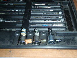
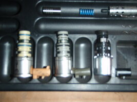
I'm talking about the electro-mechanical valves in the ends of the valve body, one is grey and the other is white/tan. They look identical on the outside and the manual indicates they are both normally-closed.

So what's the difference?
 

Reprise

Lifetime VIP Donor
Supporting Donor
Member
Jul 22, 2015
2,724
Just from a layman's standpoint... the PWM Valve cycles a lot more frequently than the other one. That's why the valve body bore wears / widens in that area, lowering fluid pressure, and the resultant problems from that. The cycling puts (a managed amount of) slip in the converter, mostly for improved fuel mileage, along with a little bit of shift shock elimination (NVH) so you don't feel the thing constantly going in / out of lockup (3rd as well as 4th / OD).

The 3-2 valve should be used for kickdown (mostly when you're coasting / braking, and the logic determines that you'd be better downshifting to second, if you start accelerating again). There's a 3-1 kickdown, too (same basic purpose).

That's about as much as I can guess, TBH. Let's see who else chimes in.
 

JayArr

Original poster
Member
Sep 24, 2018
515
Mission BC Canada
I guess what I'm asking is why are there two part numbers and are they interchangeable?

Left = OEM 2-3
Middle = OEM PWM
Right = replacement PWM
 

Attachments

  • P5080005.JPG
    P5080005.JPG
    567.3 KB · Views: 3
  • P5080006.JPG
    P5080006.JPG
    323.6 KB · Views: 3
Last edited:
Sep 17, 2018
30
Iowa
There are 2 style solenoids across years
On/Off vs PWM
93/94= PWM 3-2///NO TCC
95= PWM 3-2///PWM TCC
96-08=On/Off 3-2///PWM TCC
09+=NO 3-2///PWM TCC


The easiest way to ID them is the PWM has a white connector (often turns pink/orangeish after being in fluid for a long time)
The On/Off has a grey/black connector

Alternatively, you can OHM test them
On/Off=20-31 ohms
PWM=10-15 ohms
 

JayArr

Original poster
Member
Sep 24, 2018
515
Mission BC Canada
Thanks Maroon, I had no idea you could ID them by their coil resistance! That's the kind of helpful hint this forum is great for!

Trouble is that now I'm really confused. My OEM grey one is 11 ohms and it's replacement is black and measures 10.5 ohms I thought this was the PWM.

The other is white but the connector has turned orange and it is 22 ohms and I have it labelled 3-2.

Edit:

Could you have your colors reverse Maroon? Sonnax says the grey one is PWM (10-15 ohms) and the white/org one is 3-2 (20-31 ohms)
 

mrrsm

Lifetime VIP Donor
Supporting Donor
Member
Oct 22, 2015
7,773
Tampa Bay Area
This ATSG Diagnostic Manual may add some insights:
 

Attachments

  • 4L60E_80E_CODE_BOOK.pdf
    3.8 MB · Views: 2
Sep 17, 2018
30
Iowa
Thanks Maroon, I had no idea you could ID them by their coil resistance! That's the kind of helpful hint this forum is great for!

Trouble is that now I'm really confused. My OEM grey one is 11 ohms and it's replacement is black and measures 10.5 ohms I thought this was the PWM.

The other is white but the connector has turned orange and it is 22 ohms and I have it labelled 3-2.

Edit:

Could you have your colors reverse Maroon? Sonnax says the grey one is PWM (10-15 ohms) and the white/org one is 3-2 (20-31 ohms)
I should have stuck to the ohms, not colors.
Because GM had the early units all use white connectors.
Then in 96 they switched to the gray being pwm and white being on/off

So yes, my colors are backwards.
Grey/Black=pwm
White/orange=on/off

UNLESS you're looking at 93-95
 

Forum Statistics

Threads
23,352
Posts
638,256
Members
18,560
Latest member
Gdub2306

Members Online