Multimeter voltage question at fuses

Elizabetty

Original poster
Member
Dec 2, 2022
191
Wisconsin
I'm playing with my multimeter in the rear fuse box. I determined the reason I had no voltage to the turn signal was because I needed to actually use the switch and turn the turn signal on. Once doing that I had voltage on both sides of the top pins with the fuse in the box. However, the voltage rapidly fluctuates with very high and low readings. If I compare this to the radio for example, I have a steady voltage reading on each top fuse pin. I have the correct amount of voltage going into the fuse block and fuses that hold steady so far show expected voltage. I'm not sure what it means when the voltage is jumping all over the place and I've confirmed it's not my multimeter or my leads or my connection point for ground.

I have watched videos supplied on this site and I have not seen this specific scenario addressed. It's typically voltage on one half of the fuse and none on the other, low voltage or no voltage at all. Feel free to send me a link I may have overlooked.

What would cause voltage to be jumping all over the place?
 

budwich

Member
Jun 16, 2013
2,060
kanata
You are not really using your meter correctly. IF I understand what you are doing, you are putting the black probe on one side of the fuse location and the red on the other side. IF so, the result that you are getting is likely. In this test configuration, you are basically trying to measure voltage across the fuse. BUT this "technique" is not very sound without knowing something about the circuits attached to both those contact points. A "normal" voltage test with a meter uses the black as a reference point to a KNOWN ground. IF that does not happen, then the resulting test will have results that are well... "UNKNOWN" so to speak since there is no reference for the meter to reference to. In this case, all that you are seeing is the "chop" of the turn signal's flashing unit.... basically "AC" of a "DC" voltage... :smile:
 
  • Like
Reactions: mrrsm

Elizabetty

Original poster
Member
Dec 2, 2022
191
Wisconsin
You are not really using your meter correctly. IF I understand what you are doing, you are putting the black probe on one side of the fuse location and the red on the other side. IF so, the result that you are getting is likely. In this test configuration, you are basically trying to measure voltage across the fuse. BUT this "technique" is not very sound without knowing something about the circuits attached to both those contact points. A "normal" voltage test with a meter uses the black as a reference point to a KNOWN ground. IF that does not happen, then the resulting test will have results that are well... "UNKNOWN" so to speak since there is no reference for the meter to reference to. In this case, all that you are seeing is the "chop" of the turn signal's flashing unit.... basically "AC" of a "DC" voltage... :smile:
I have the negative test lead on a determined good ground. I have the positive test lead showing approximately 14 volts to the fuse box. I then move my positive red lead to one top of a radio fuse and see voltage matching what is coming into the fuse box. The same voltage shows on the other pin. When the turn signal is not on, there is no voltage to either side of the pin as expected until it is activated by turning the turn signal on. Then when testing each spot on top of the fuse, I have fluctuating voltage.
 

Elizabetty

Original poster
Member
Dec 2, 2022
191
Wisconsin
I have the negative test lead on a determined good ground. I have the positive test lead showing approximately 14 volts to the fuse box. I then move my positive red lead to one top of a radio fuse and see voltage matching what is coming into the fuse box. The same voltage shows on the other pin. When the turn signal is not on, there is no voltage to either side of the pin as expected until it is activated by turning the turn signal on. Then when testing each spot on top of the fuse, I have fluctuating voltage.
I posted how I was using my multimeter and then saw this post that I should have quoted. I believe I am using it correctly?
 

budwich

Member
Jun 16, 2013
2,060
kanata
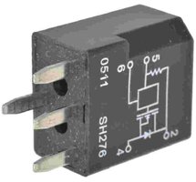
ok.... sorry my mistaken read. Ultimately, as has being stated the flasher is doing is job to make the signal blink.... which you have confirmed with your reading. And with the new "knowledge" that there is a flasher in the circuit under test, you have the rest of the story.... maybe :smile:
 
  • Like
Reactions: Elizabetty

Mooseman

Moderator
Dec 4, 2011
25,387
Ottawa, ON
For something like this, a test light is better so you would see it blink :wink:
 

Forum Statistics

Threads
23,351
Posts
638,252
Members
18,560
Latest member
Gdub2306

Members Online