Sparky
Member
- Dec 4, 2011
- 12,927
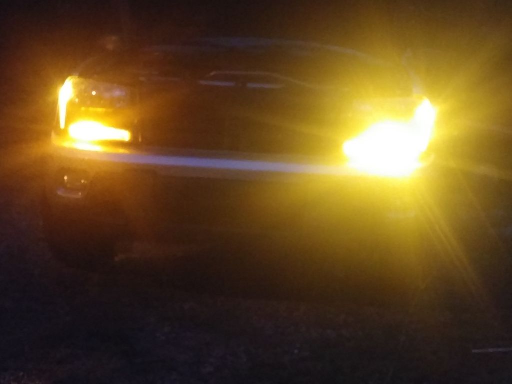
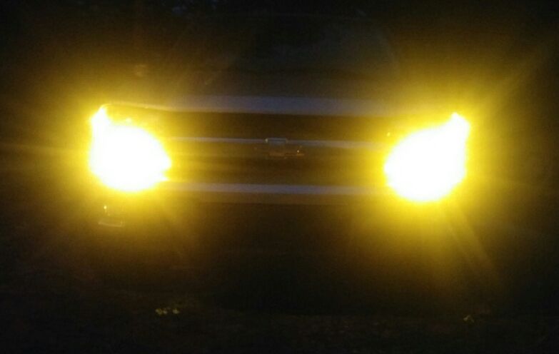
Sort of both, on the underside of the hood, shining downward into the bay.
I also want to put two rows in the bed, one on each side, to light it up at night.
I also want to put two rows in the bed, one on each side, to light it up at night.


 I would be mad as hell!! Any idea which component has failed? Hopefully it's something like a bad solder joint and something became disconnected that you could somewhat easily fix.


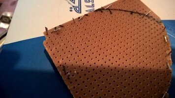
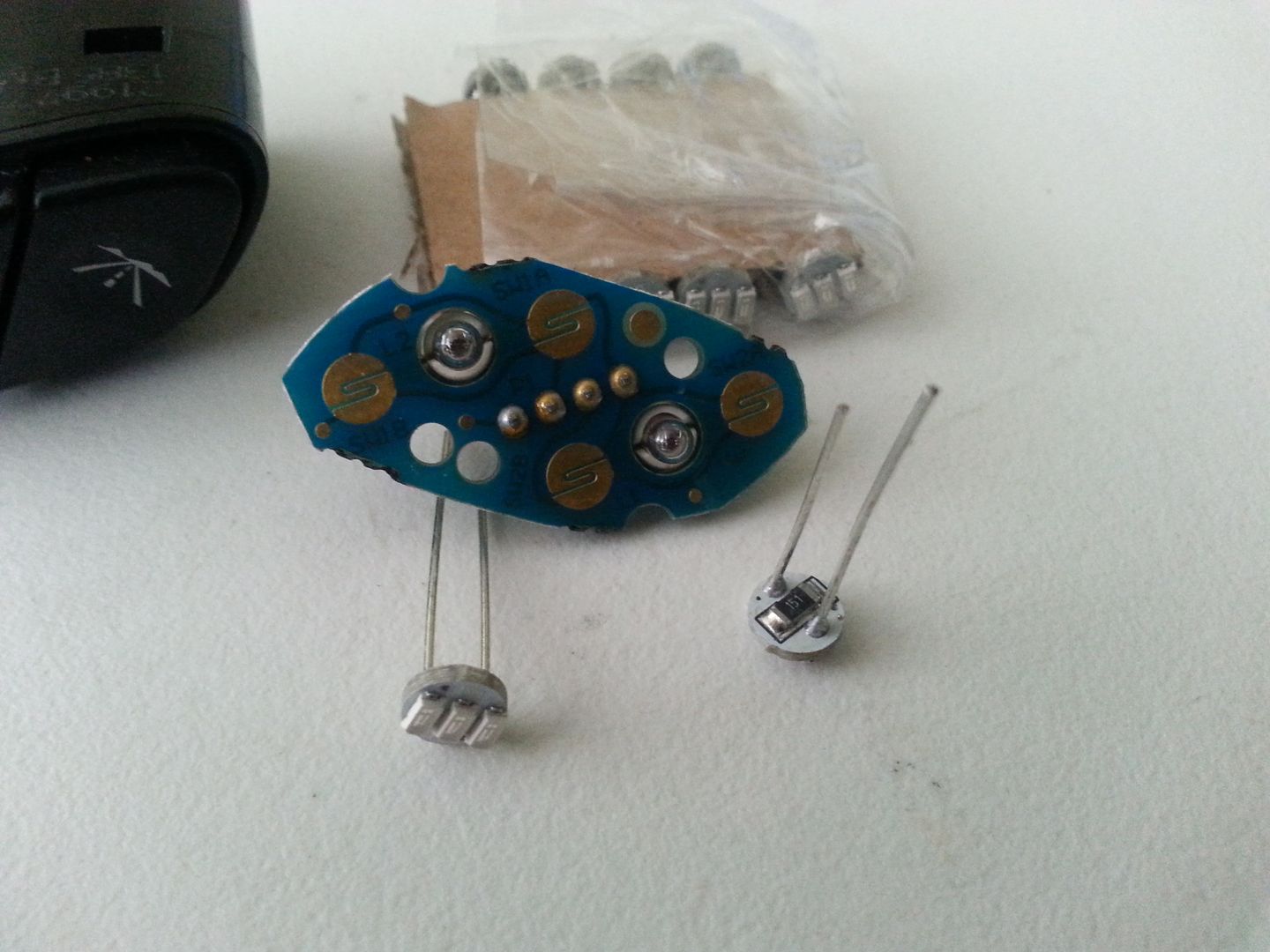
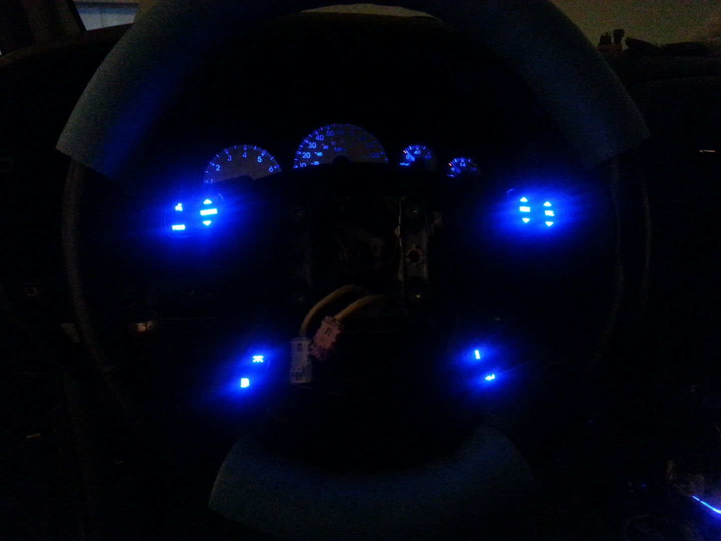
 So much unused space!!


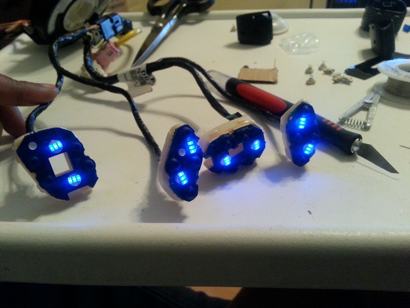

 I was able to get it back on, but I don't know how secure, so I didn't use that one.
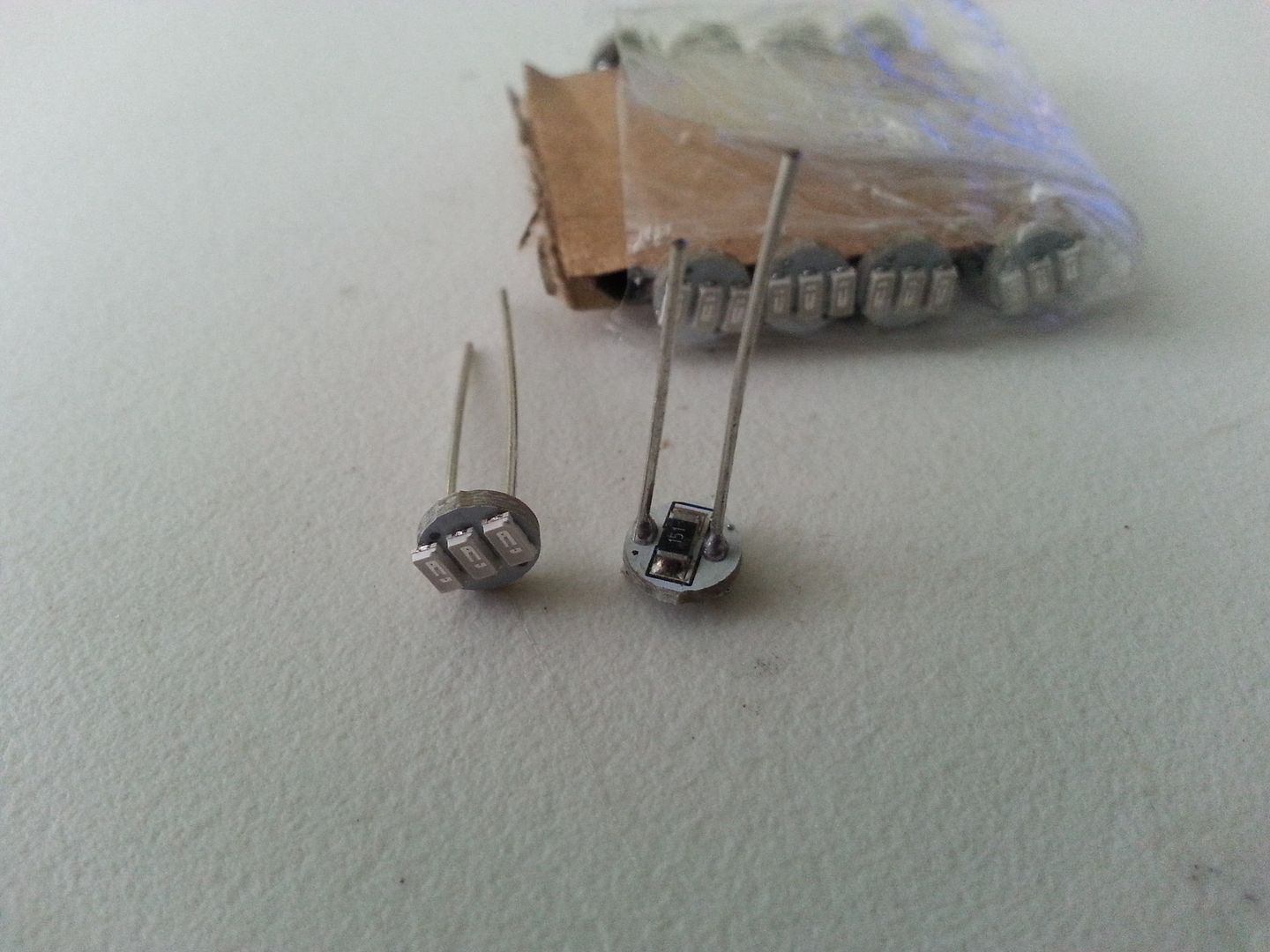
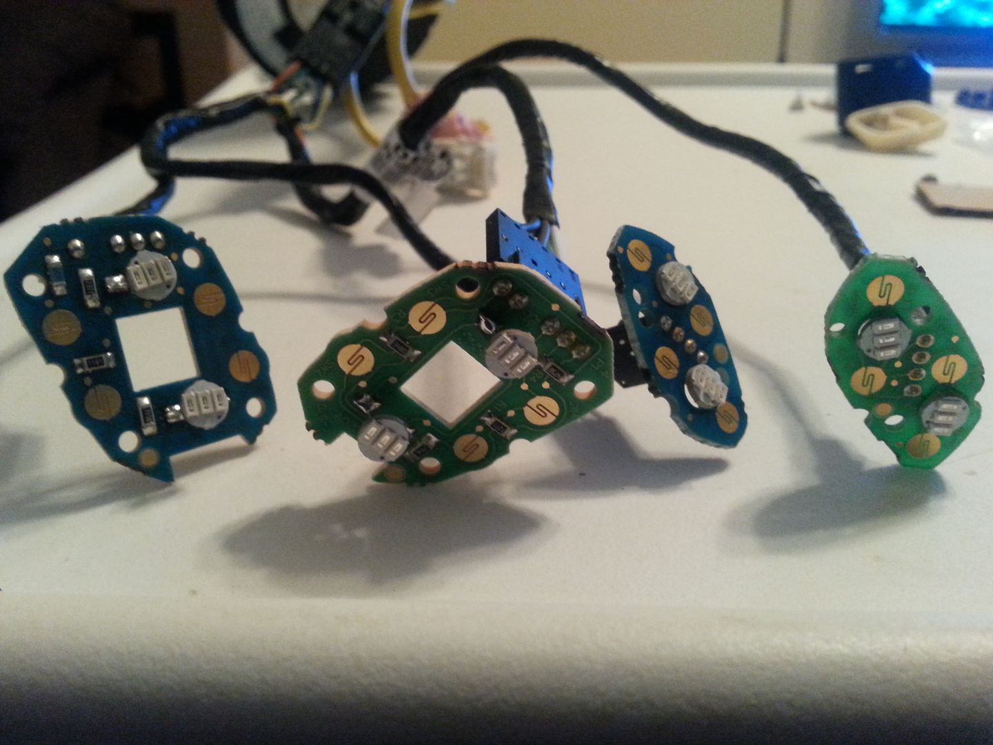
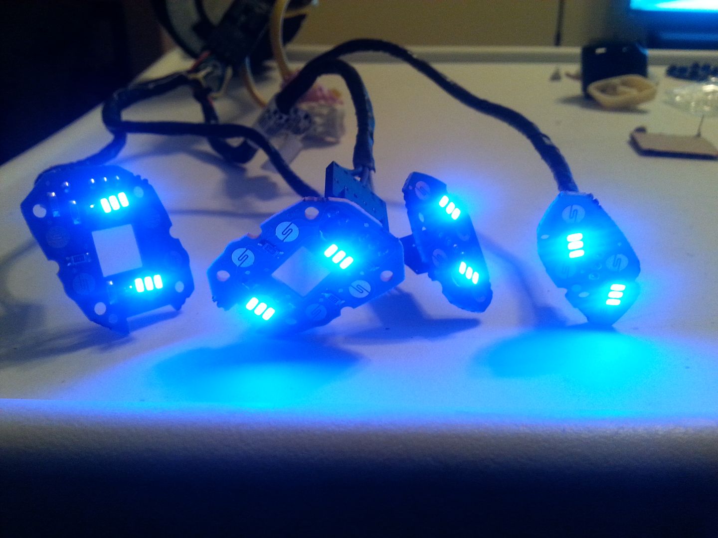
 I am seriously considering buying more, and dumping the rest of the Ebay specials in the EXT, as there are a few that have died and need to be replaced.


