In this write-up I am going to figure my way through re-wiring the power memory seats from an LTZ to work in my LS.
(If anyone needs the memory modules, I have extras lying around).
Parts/Tools:
2x Power memory seats from an '02 LTZ
1x Inline 30A fuse
1x Male power seat connector (for the passenger's side)
A couple feet of wire (a thick gauge is recommended, I used 14 ga.)
Soldering Iron, Electrical Tape, Plastic Conduit*, Zipties*, etc
Spade Connectors*
Screwdrivers
Picks*
8x 5-pin 30A relays (4x per seat, for the 4-way lumbar controls)
19mm socket and/or 19mm wrench
13mm deep socket
*Not necessary, but useful
Note: This wiring will be slightly different for '04+ seats.
The newer seats do not seem to have 4-way lumbar, so they have a different switch.
Difficulty:
Moderate. It's more tedious than challenging. Basic knowledge of electronics is required.
Time:
A few late weeknights.
DAY 1
To begin, wiring these factory-style would be too impractical and costly due to probably needing to get the BCM re-flashed to support the seats, plus, needing to re-create the factory wiring harnesses.
The power seat connector is existing on my driver's side, but it only has the wires for the seat belt sensor and, oddly enough, it already has the thick ground wire which gets grounded in the left B-pillar- G302.
(Tip: Disconnecting the seat belt sensor seems to make the system think your seat belt is always buckled).
The passenger side has no connector at all because no seat belt sensor (this is where the male connector I salvaged comes in to play).
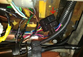
When the front seats are removed, a break in the carpet can easily be lifted to allow wiring to be run under the floor. Due to the close proximity to the rear fuse block, just running power to each seat will be a piece of cake.
All factors considered, re-wiring the seats to remove memory functionality will be the simplest and cheapest way to do this.
Procedure:
I will now disassemble the driver's power seat:
3x 19mm nuts and 1x 19mm bolt holds the seat to the floor.
6x Phillips screws hold the side trim/controls to the seat.
4x 13mm nuts hold the seat bottom to the frame.
1x Phillips screw holds the memory module to the underside of the seat.
Assessing the parts I have, it appears as though the seat controls are the same between Memory and Non-Menory seats - that's good. The only difference being that Memory seats have a memory module separating the motors from the switches, raining on my plug n' play parade.
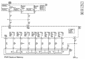
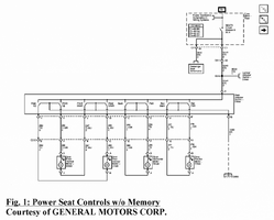
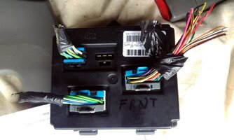
That's okay though, I just completed the "memory module delete" mod.
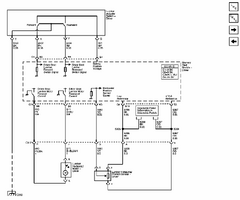
Next, I marked-up Figure 45 from the 2002 Wiring PDF (thanks for the PDFs Mooseman).
This shows what parts/wires I will be using or ignoring.
(The wires I have labeled with a plus (+) connect to the respective wires labeled with an 'o' (o). Those two added symbols do not indicate polarity, the motors spin forward/backward depending on the direction of current).
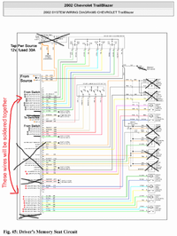
(All colors here match up to what I have except for "D5" in the "From Switch" connector. It is actually orange, not red/white)
The Lumbar switch does not have a ground connection like the Seat Control switch. I searched all over the internet, and from what I can see, there is oddly no ground anywhere in the lumbar circuits.
My best guess is that, unlike the seat controls, the lumbar motors are grounded by the memory module when the appropriate button is pressed.
No big deal, this issue can be solved using the 5-pin 30A relays.
This diagram shows how I wired up one set of lumbar functions- in/out:
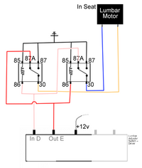
(Wire colors may not be accurate)
When one control is pressed, this set of relays completes the circuit by grounding the other side.
DAY 2
Time to get to work. First thing is to pull apart the wiring harness so we have only the wires we need.
I now need to verify that Figure 45 was correct by matching the wires to their function.
Using a multimeter to test for continuity, I was able to identify and group the switch wires by function and conclude that Figure 45 was correct.
(Here I am testing the front Up/Down switch)
Now that all wires to the switches are identified, I can proceed.
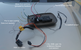
Now, I want to make sure the motors on the seats actually work.
The small gauge wires on the back of the motors are the sensors. They can be cut/removed.
The thick gauge wires run the motor. A quick and dirty test with some jumpers proves the motors move in both directions.
The wires from the switches are much thinner than the power wires to the motors. I don't want to create a heating element!
I can proceed one of two ways:
1) Introduce more relays into the equation
or
2) Upgrade the wiring gauge to the switches (since the switches seem to be able to handle the full power in the Non-Memory application)
Both approaches have their pros and cons. I will choose #2 because I like the challenge (and I don't want to wait until next week for some relays to ship).
DAY 3
After not being able to find larger connector pins at Napa, I will have to deal with what I have.
This is not ideal, but I will be popping the pins out, cutting the ~20 ga. wire off of them, and soldering larger 14 ga. wire to them.
Here, I have the ~10 ga. power and ground wires already clipped in, as well as the first of the 14 ga. wires to the motors.
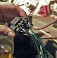
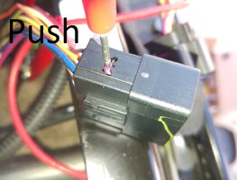
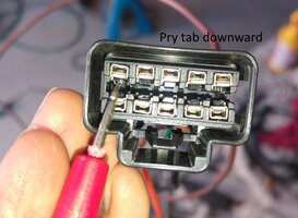
How to remove wires/pins from a GM connector:
I attached the wires for the horizontal movement and plugged in the switch to test them out.
Success!
The seat functions with no BCM or Memory module, and it didn't catch on fire!
Now install the rest of the wiring.
The completed connector fits extra snug due to how thick the new wires are:
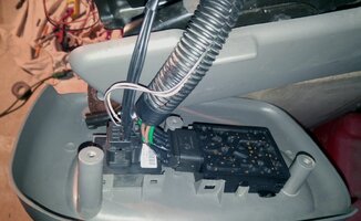
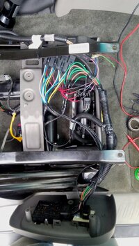
This next image shows the completed passenger-side seat wiring.
The four 5-pin relays operate the lumbar motors. Two control up/down, two control in/out.
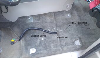
Last but not least, we have to create a vehicle-side wiring harness. I used the existing seat connector and just popped the thick orange power wire into it (from the salvaged connector), then soldered the new power wires to the cut end.
I ran the pwr/gnd wires to the passenger side seat underneath the center console utilizing the break in the carpet (you can fish wire under the console).
The main power wire runs to the B-pillar, under the rear door step trim, then pops out by the rear fuse block and is attached to the fuse block power stud after passing through a 30A inline fuse.
Install the seat, and you're done.
That's really all there is to getting these seats working. Test your work as you go and follow the diagrams provided in this thread.
I am still dreaming up how I will go about getting the heaters working, but since I am moving south soon, this is not a priority.
(If anyone needs the memory modules, I have extras lying around).
Parts/Tools:
2x Power memory seats from an '02 LTZ
1x Inline 30A fuse
1x Male power seat connector (for the passenger's side)
A couple feet of wire (a thick gauge is recommended, I used 14 ga.)
Soldering Iron, Electrical Tape, Plastic Conduit*, Zipties*, etc
Spade Connectors*
Screwdrivers
Picks*
8x 5-pin 30A relays (4x per seat, for the 4-way lumbar controls)
19mm socket and/or 19mm wrench
13mm deep socket
*Not necessary, but useful
Note: This wiring will be slightly different for '04+ seats.
The newer seats do not seem to have 4-way lumbar, so they have a different switch.
Difficulty:
Moderate. It's more tedious than challenging. Basic knowledge of electronics is required.
Time:
A few late weeknights.
DAY 1
To begin, wiring these factory-style would be too impractical and costly due to probably needing to get the BCM re-flashed to support the seats, plus, needing to re-create the factory wiring harnesses.
The power seat connector is existing on my driver's side, but it only has the wires for the seat belt sensor and, oddly enough, it already has the thick ground wire which gets grounded in the left B-pillar- G302.
(Tip: Disconnecting the seat belt sensor seems to make the system think your seat belt is always buckled).
The passenger side has no connector at all because no seat belt sensor (this is where the male connector I salvaged comes in to play).
When the front seats are removed, a break in the carpet can easily be lifted to allow wiring to be run under the floor. Due to the close proximity to the rear fuse block, just running power to each seat will be a piece of cake.
All factors considered, re-wiring the seats to remove memory functionality will be the simplest and cheapest way to do this.
Procedure:
I will now disassemble the driver's power seat:
3x 19mm nuts and 1x 19mm bolt holds the seat to the floor.
6x Phillips screws hold the side trim/controls to the seat.
4x 13mm nuts hold the seat bottom to the frame.
1x Phillips screw holds the memory module to the underside of the seat.
Assessing the parts I have, it appears as though the seat controls are the same between Memory and Non-Menory seats - that's good. The only difference being that Memory seats have a memory module separating the motors from the switches, raining on my plug n' play parade.


That's okay though, I just completed the "memory module delete" mod.

Next, I marked-up Figure 45 from the 2002 Wiring PDF (thanks for the PDFs Mooseman).
This shows what parts/wires I will be using or ignoring.
(The wires I have labeled with a plus (+) connect to the respective wires labeled with an 'o' (o). Those two added symbols do not indicate polarity, the motors spin forward/backward depending on the direction of current).

(All colors here match up to what I have except for "D5" in the "From Switch" connector. It is actually orange, not red/white)
The Lumbar switch does not have a ground connection like the Seat Control switch. I searched all over the internet, and from what I can see, there is oddly no ground anywhere in the lumbar circuits.
My best guess is that, unlike the seat controls, the lumbar motors are grounded by the memory module when the appropriate button is pressed.
No big deal, this issue can be solved using the 5-pin 30A relays.
This diagram shows how I wired up one set of lumbar functions- in/out:

(Wire colors may not be accurate)
When one control is pressed, this set of relays completes the circuit by grounding the other side.
DAY 2
Time to get to work. First thing is to pull apart the wiring harness so we have only the wires we need.
I now need to verify that Figure 45 was correct by matching the wires to their function.
Using a multimeter to test for continuity, I was able to identify and group the switch wires by function and conclude that Figure 45 was correct.
(Here I am testing the front Up/Down switch)
Now that all wires to the switches are identified, I can proceed.

Now, I want to make sure the motors on the seats actually work.
The small gauge wires on the back of the motors are the sensors. They can be cut/removed.
The thick gauge wires run the motor. A quick and dirty test with some jumpers proves the motors move in both directions.
The wires from the switches are much thinner than the power wires to the motors. I don't want to create a heating element!
I can proceed one of two ways:
1) Introduce more relays into the equation
or
2) Upgrade the wiring gauge to the switches (since the switches seem to be able to handle the full power in the Non-Memory application)
Both approaches have their pros and cons. I will choose #2 because I like the challenge (and I don't want to wait until next week for some relays to ship).
DAY 3
After not being able to find larger connector pins at Napa, I will have to deal with what I have.
This is not ideal, but I will be popping the pins out, cutting the ~20 ga. wire off of them, and soldering larger 14 ga. wire to them.
Here, I have the ~10 ga. power and ground wires already clipped in, as well as the first of the 14 ga. wires to the motors.

How to remove wires/pins from a GM connector:
I attached the wires for the horizontal movement and plugged in the switch to test them out.
The seat functions with no BCM or Memory module, and it didn't catch on fire!
Now install the rest of the wiring.
The completed connector fits extra snug due to how thick the new wires are:

This next image shows the completed passenger-side seat wiring.
The four 5-pin relays operate the lumbar motors. Two control up/down, two control in/out.

Last but not least, we have to create a vehicle-side wiring harness. I used the existing seat connector and just popped the thick orange power wire into it (from the salvaged connector), then soldered the new power wires to the cut end.
I ran the pwr/gnd wires to the passenger side seat underneath the center console utilizing the break in the carpet (you can fish wire under the console).
The main power wire runs to the B-pillar, under the rear door step trim, then pops out by the rear fuse block and is attached to the fuse block power stud after passing through a 30A inline fuse.

Install the seat, and you're done.
That's really all there is to getting these seats working. Test your work as you go and follow the diagrams provided in this thread.
I am still dreaming up how I will go about getting the heaters working, but since I am moving south soon, this is not a priority.
Attachments
Last edited:

