NP... Deleted.... However... You should know that in the latter of those 65 Images...the importance of what happens whenever the Brake Pedal is stepped upon in relation to the TCC Activity in response may be integral to other aspects of things.
You are using an out of date browser. It may not display this or other websites correctly.
You should upgrade or use an alternative browser.
You should upgrade or use an alternative browser.
Intermittent PRDNL Indicator Weirdness, P0700 and other Goodness
- Thread starter spfautsch
- Start date
its the new bluetooth wifi solderthe "miracles" of lead free solder.... maybe.
NP... Deleted.... However... ... in the latter of those 65 Images...
I appreciate your input here, but I didn't make it past the first 10 images. At the time I had bigger fish to fry. They're fried now, read on.
the importance of what happens whenever the Brake Pedal is stepped upon in relation to the TCC Activity in response may be integral to other aspects of things.
That's an interesting tangent I've thought about but not in great detail. That input is a +12v signal, so if it's shorting to another power source that could be worth investigating. If it's broken / going open or shorting to ground it shouldn't make any difference. Also, it doesn't really explain why the previous TCM module eventually failed completely, setting persistent RAM verification errors. Or, why this problem seems to be directly related to temperature.
Edit: To further clarify, the previous TCM dying seems to a me a sign that whatever is happening is causing the TCM's voltage regulator / power supply filtering to be overtaxed, causing "dirty" power to the processor and memory of the TCM and subsequently causing the processor to reboot due to low voltage.

Almost ready to test. If this doesn't work it'll make good nesting material for all the birds living in my back yard.
Last edited:
Well... Since I'm Batting a Thousand so far with NOT rendering any useful information to this Thread... I'll give this once last try...
Check Out @MAY03LT 's contribution shown in Post # 2 via THIS Link:
 gmtnation.com
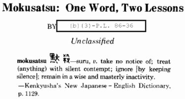
But from hereon out... it will be a "Mokusatsu" situation... 黙 殺

Check Out @MAY03LT 's contribution shown in Post # 2 via THIS Link:
The 5 Transmission p codes
I seen the video on this subject from GMTnation, I cannot find anything on it here to help me I am new to the site. I have the five P0740 p0753 p0758 p0785 p1860. I tested fuse 47 it has power both sides. I swapped an ignition switch from my 02 envoy that I had smashed up. Reset codes and...
But from hereon out... it will be a "Mokusatsu" situation... 黙 殺

Last edited:
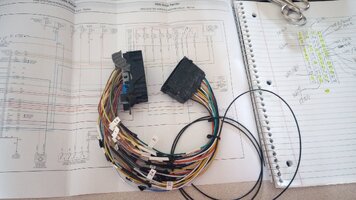
Appreciated, but already have page 164 and 166 of the 2006 Ranier 'WIRING.PDF' service manual printed in color, cut and taped together, in duplicate. It's what's in the background underneath the break-out cable and has every circuit connected to the TCM.
Edit: One thing the diagram you referenced got me thinking about - it, and most of the other references including the 2006 Ranier PDF collection - incorrectly depict the D2 switch in the manifold pressure switch (most trans guys refer to this as the "pillow switch"). It is in fact a normally closed switch, which when D2 applies breaks the circuit grounding the D4 / D3 normally open switches. I got some white-out and fixed my printed copies so as not to chase ghosts should I get to looking at this one.
Got Rusty out of storage this morning and have the break-out cable and the newest TCM module in place. Starts and runs with no issues. That's as far as I got b/c I threw my back out pulling weeds this morning and after mowing my lawn that's about as far as I'm able to get.
Have a Hantek CC65 clamp-on current sensor on the way that should make visualizing solenoid currents much easier. Just need to find my BNC extension cable so I can feed it through the firewall along with some home-made test clip leads.
Edit: One thing the diagram you referenced got me thinking about - it, and most of the other references including the 2006 Ranier PDF collection - incorrectly depict the D2 switch in the manifold pressure switch (most trans guys refer to this as the "pillow switch"). It is in fact a normally closed switch, which when D2 applies breaks the circuit grounding the D4 / D3 normally open switches. I got some white-out and fixed my printed copies so as not to chase ghosts should I get to looking at this one.

Got Rusty out of storage this morning and have the break-out cable and the newest TCM module in place. Starts and runs with no issues. That's as far as I got b/c I threw my back out pulling weeds this morning and after mowing my lawn that's about as far as I'm able to get.
Have a Hantek CC65 clamp-on current sensor on the way that should make visualizing solenoid currents much easier. Just need to find my BNC extension cable so I can feed it through the firewall along with some home-made test clip leads.
Last edited:
Mooseman
Moderator
For manuals and schematics, have you tried this site?
Free Car Service Manuals from Operation CHARM — No strings attached!
Operation CHARM provides completely free repair/service/workshop manuals for over 50,000 models of cars and trucks manufactured 1982-2013. No sign-up or paywall.
charm.li
I haven't seen or heard of that, thanks! May come in handy some day.
Whatever the case, they all seem to basically be the same data packaged differently. I have to wonder how that information is licensed out, or if it's something freely available from the OEMs.
The first schematic I found on that site also incorrectly depicts the pillow switch, which I will add also has a normally closed switch for D3, according to this manual which apparently came directly from GM. (lower left corner, page 37)
Hydra-matic 4L60-E Tech Guide
You might want to add that to your manuals page as it seems slightly more comprehensive than the ATSG version.
Mooseman
Moderator
NP, happy to contribute.
Think my toolbox is finally equipped to tackle this problem.

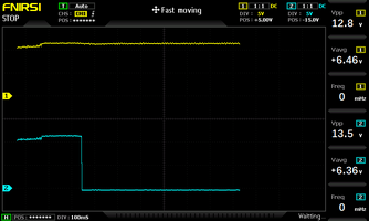
Channel 1 is the switched IGN voltage that supplies power to the trans solenoids, and channel 2 is the 1-2 shift solenoid output. This was taken moments after starting the engine - the voltage jump at the beginning of the capture is the alternator starting to generate power. Interesting that the 1-2 shift solenoid is only energized after quite a bit of time has passed after key-on. I'll have to try quantifying that.
This isn't a lab grade DSO, but I wish I would have bought one of these years ago. There's no external trigger for the freeze / run function (that stops the sweep), but I'll get by with the big red button on the scope.
Think my toolbox is finally equipped to tackle this problem.

Channel 1 is the switched IGN voltage that supplies power to the trans solenoids, and channel 2 is the 1-2 shift solenoid output. This was taken moments after starting the engine - the voltage jump at the beginning of the capture is the alternator starting to generate power. Interesting that the 1-2 shift solenoid is only energized after quite a bit of time has passed after key-on. I'll have to try quantifying that.
This isn't a lab grade DSO, but I wish I would have bought one of these years ago. There's no external trigger for the freeze / run function (that stops the sweep), but I'll get by with the big red button on the scope.
Last edited:
